

Hardware Introduction
AlphaBot 2 is a wheeled dual-arm humanoid robot from AI² Robotics’ AlphaBot series, powered by the embodied foundation model — Alpha Brain. It features exceptional spatial intelligence and strong learning capabilities, enabling it to quickly adapt to new environments and flexibly perform a wide range of human-like tasks.
Overall Structure and Parameters
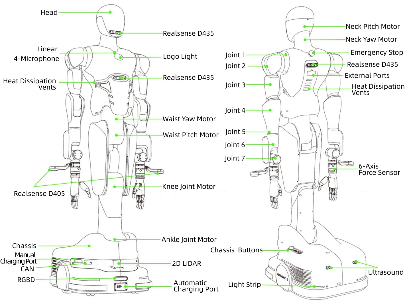
Section titled “Overall Structure and Parameters”AlphaBot 2 has a total of 22 degrees of freedom (excluding end effectors). The legs adopt a three-joint folding lifting structure with waist yaw, each robotic arm has 7 degrees of freedom, the neck supports 2 degrees of freedom (pitch and yaw), and the chassis is driven by two-wheel differential drive.
| Category | Name | Specification |
|---|---|---|
Basic Parameters | Height | 1800mm |
Weight | 135kg (standard configuration) | |
Computing Module | NVIDIA Orin AGX 64G | |
Battery Life | 4~6h | |
Battery | 48V 30Ah | |
Full Body DOF | 22 (excluding end effectors) | |
Robotic Arm DOF | 7 (single arm) | |
Single Arm Span | 723mm (excluding end effectors) | |
Rated Payload | 4kg (single arm) | |
Working Space | 0~2.3m | |
Moving Speed | 0.1m/s~1.5m/s | |
Slope | 0°~5° | |
Hardware Parameters | Head, Chest, Back Cameras | Realsense D435 |
Hand Cameras | Realsense D405 | |
Chassis Drive Method | Two-wheel differential | |
End Effectors | Dexterous hand / Gripper / Other tools | |
Voice Module | MIC array: linear MIC*4 | |
Screen | Interactive display screen | |
Debugging Ports | USB3.0*1; HDMI*1; RJ45*1 | |
Emergency Stop Device | Emergency stop on the back | |
Operating Environment | Temperature | 5℃~40℃ |
Humidity | 10~80%RH |
Component Functions and Specifications
Section titled “Component Functions and Specifications”This section provides detailed descriptions of the main hardware components of AlphaBot 2.
Vision System
Section titled “Vision System”-
The head, chest, and back of AlphaBot 2 are each equipped with a Realsense D435 camera, providing comprehensive visual perception. The Realsense D435 is an RGB-D camera capable of capturing real-time color and depth information (distance between objects and the camera), delivering critical data for functions such as object recognition and human-robot collaboration.
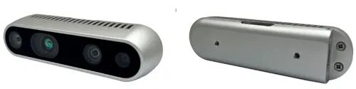
Name Specification Stereo Baseline 50mm Depth Sensor Technology Global Shutter Depth Field of View 87°×58° Max Depth Resolution 1280×720 @ 30fps Z-axis Accuracy Error <2% (at 2m) RGB Sensor Technology Rolling Shutter Maximum RGB Resolution 1920×1080 @ 30fps RGB Field of View 69°×42° Z-axis Minimum Distance Approx. 28cm Ideal Working Range 0.3~3m Size, Weight 90×25×25mm, 72g -
The ends of the left and right robotic arms are each equipped with a Realsense D405 camera, specifically used for close-range object recognition. The Realsense D405 captures real-time color details and spatial attitude information of target objects at close range, providing real-time visual guidance for end operations.
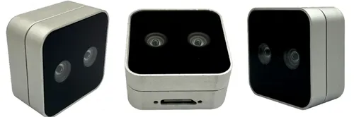
Name Specification Binocular Baseline 18mm Depth Sensor Technology Global Shutter Depth Field of View 87°×58° Maximum Depth Resolution 1280×720 @ 30fps Z-axis Accuracy Error <2% (at 500mm) RGB Sensor Technology Global Shutter Maximum RGB Resolution 1280×720 @ 30fps RGB Field of View 87°×58° Z-axis Minimum Distance Approx. 70mm Ideal Working Range Approx. 70~500mm Size, Weight 42×42×22mm, 58g
Joint Motors
Section titled “Joint Motors”The zero position of the robot is shown in the figure below, where the rotation angle direction of the torso joint motor is shown in the figure.
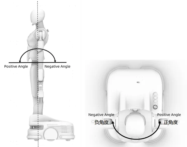
Key joint parameters are provided in the following table.
| Component | Name | Range of Motion | Reduction Ratio | 2000rpm/Rated Torque | Peak Torque |
|---|---|---|---|---|---|
| Head | Neck Pitch Motor | -16°~13° | 51 | 1.8Nm | 3.3Nm |
| Neck Yaw Motor | -90°~90° | 51 | 1.8Nm | 3.3Nm | |
| Waist | Waist Yaw Motor | -90°~90° | 101 | 30Nm | 66Nm |
| Waist Pitch Motor | -90°~30° | 121 | 84Nm | 207Nm | |
| Leg | Knee Joint Motor | 0°~148° | 121 | 169Nm | 436Nm |
| Ankle Joint Motor | -58°~0° | 121 | 169Nm | 436Nm |
Robotic Arms
Section titled “Robotic Arms”AlphaBot 2 is equipped with a dual robotic arm system, each with 7 degrees of freedom, enabling flexible operation and diverse task execution. The robotic arms adopt high-precision servo motors and joint designs to ensure stability and reliability in various operating environments. The end effectors of the robotic arms can be replaced with dexterous hands, grippers, or other tools according to task requirements to adapt to different operating scenarios.
Specifications
Section titled “Specifications”The following table lists the main specifications for a single robotic arm.
| Name | Specification |
|---|---|
| Degrees of Freedom | 7 |
| Joint Ranges | J1:-178°~178° J2:-25°~178° J3:-178°~178° J4:-130°~0° J5:-178°~178° J6:-70°~70° J7:-26°~120° |
| Effective Rated Load | 4kg |
| Working Radius | 723mm (excluding end effector) |
| Repeat Positioning Accuracy | ±0.1mm |
| Six-Axis Force Range | 200N/7Nm |
| Supply Voltage | DC 20~30V |
| Supply Current | 20A |
| External Hardware Interfaces | Ethernet / RS485 / CAN |
| External Software Interfaces | Python, C, and C++ |
Function Description
Section titled “Function Description”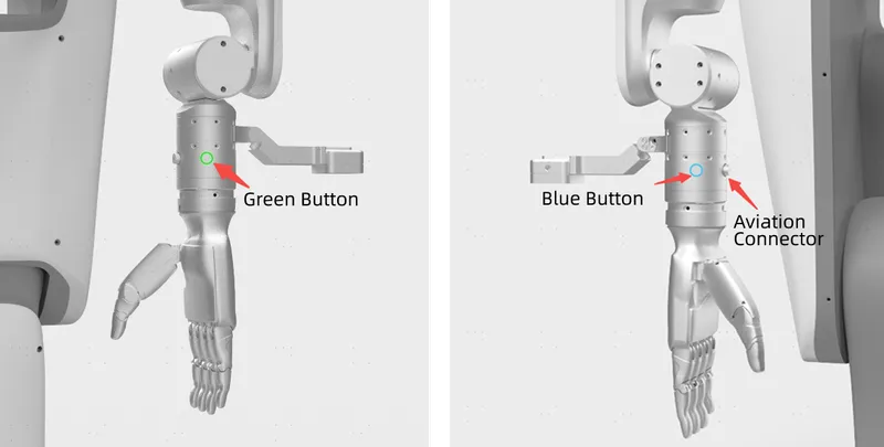
| Name | Description |
|---|---|
| Green Button | Drag teaching; press and hold to enter drag teaching mode. |
| Blue Button | Reproduce/zero; click to reproduce the drag teaching trajectory, press and hold to return to zero position. |
| Aviation Connector | Connects end effectors, such as grippers, dexterous hands, or suction cups. |
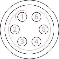
Pin definitions for the aviation connector are as follows:
| Pin Number | Wire color | Description |
|---|---|---|
| 1 | Yellow | RS485_A |
| 2 | White | RS485_B |
| 3 | Red | Digital interface 1 (DI1/DO1) |
| 4 | Black | Digital interface 2 (DI2/DO2) |
| 5 | Green | Power GND |
| 6 | Blue | Power output: 0 V/12 V/24 V, controllable by program |
Chassis
Section titled “Chassis”The chassis adopts a two-wheel differential drive, enabling flexible movement and steering. The differential drive system controls the speed of the left and right wheels, allowing the robot to perform various motion modes such as forward/backward movement, turning, and in-place rotation, thereby meeting navigation requirements in complex environments.
Specifications
Section titled “Specifications”The following table lists the main specifications for the chassis.
| Name | Specification |
|---|---|
| Drive Method | Two-wheel differential |
| Global Positioning Accuracy | ±5cm |
| Width | 505mm |
| Length | 650mm |
| Payload | ≤100kg |
| Speed | 0.1m/s~1.5m/s |
| Auto-recharging | Supported |
| Battery Capacity | 48V 30Ah |
| LiDAR | 2D LiDAR, measuring range up to 25 m |
| RGBD Camera | 1 |
| Debugging Ports | RJ45, USB, HDMI |
| Software Interface | API |
Functional Description
Section titled “Functional Description”-
Chassis buttons or knobs.
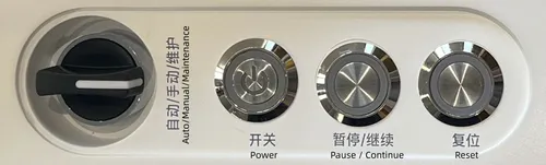
Name Description AutoMode for autonomous robot movement. In this mode, tasks or task groups can be sent to the robot, which will automatically execute the pre-programmed combined commands. In this mode, the chassis status light is white. Manual Mode for manually controlling robot movement. In this mode, the robot can be pushed, and the chassis status light is yellow. Maintenance In this mode, the power of the overall motion module is cut off, the robot and integrated mechanism cannot be controlled to move, and the chassis status light is red. Power Press and hold for 1.5s to power on or off the robot. Pause/Continue When an abnormality occurs, press the Pause/Continuebutton, the robot will pause the current task, and the chassis status light will be white trailing flowing. When connected to the LAN Wi-Fi, press and hold this button, and the robot will broadcast the current IP address by voice.Reset Short press to reset the robot to the previously recorded coordinate point. Long press to reset the robot to the preset initial reset point. Combination Button Simultaneously long press the Pause/Resume and Reset buttons for 5 seconds to activate the robot’s hotspot (for connection by the chassis upper computer software), accompanied by a voice prompt. -
Chassis external ports.
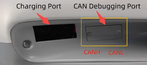
Name Description Charging Port Connects the power adapter to charge the robot. CAN Debugging Port When motor anomalies require inspection, remove the external CAN port cover. Use a CAN cable and CAN analyzer to view and adjust the status parameters of joint motors.
Computing Module
Section titled “Computing Module”AlphaBot 2 is equipped with an NVIDIA AGX Orin 64G as its computing module, providing substantial computational power to support intelligent decision-making and task execution in complex environments.
| Name | Description |
|---|---|
| Control Board | NVIDIA AGX Orin 64GB |
| Operating System | Ubuntu 22.04 LTS |
Rear Back
Section titled “Rear Back”The rear back of AlphaBot 2 integrates external ports and an emergency stop device.
-
External ports: Remove the cover to access ports for expanding external devices.
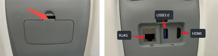
Port Quantity Description HDMI 1 Connects to a monitor or other video output device for convenient debugging and monitoring. USB 3.0 1 Connects external devices such as cameras or sensors, supporting high-speed data transfer. RJ45 1 Enables direct communication with the robot controller via an Ethernet cable. -
Emergency Stop Device: Press the emergency stop button, the chassis will brake, and the robotic arm will stop moving; turn clockwise to release the emergency stop.

Power Adapter
Section titled “Power Adapter”AlphaBot 2 is equipped with a dedicated power adapter to provide stable power supply for the robot, ensuring its continuous operation in various operating environments.
-
Power adapter specifications:
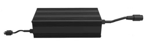
Name Specification Size 235×120×70mm Weight 3.5kg Input Cable Length 1500mm Output Cable Length 1000mm Input 200~240V,50~60HZ Output 29.4±0.2V,20A±3%,700W -
LED indicator status:
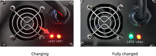
LED Color Status LED1 Red Powered on LED2 Red Charging Green Fully charged
Charging Box
Section titled “Charging Box”AlphaBot 2 is equipped with a dedicated charging box, providing a safe and convenient charging solution for the robot, ensuring its continuous operation in various operating environments.
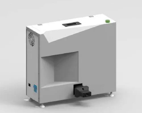
| Name | Specification |
|---|---|
| Size | 180×530×460mm |
| Input Format | Single-phase three-wire (L/N/PE) |
| Input Voltage | 220V |
| Frequency | 45Hz~65Hz |
| Maximum Input Current | ≤18A (depending on actual power) |
| Input Power Factor | ≥0.99 (full load) |
| Output Voltage | 48V |
| Output Current | 0~50A |
| Voltage Regulation Accuracy | ≤±0.6% |
| Measured Noise Voltage | <2mV |
| Peak-to-Peak Noise Voltage | ≤150mV (20 MHz bandwidth) |
| Efficiency | ≥90% (rated input, full load) |
| Working Temperature | -20°C~ 65°C (recommended 15°C~25°C) |
| Storage Temperature | -40℃~70℃ |
| Relative Humidity | 10%~90% (recommended 40%~60%) |
| Atmospheric Pressure | 70kPa~106kPa |
| Site Requirements | No serious dust, explosive dangerous media, harmful gases that corrode metals and damage insulation, conductive particles and serious mold, and no strong electromagnetic interference around |