Common Operations
Mastering the following operations will help you operate the AlphaBot 2 robot more efficiently.
Power On
Section titled “Power On”-
At the chassis, press and hold the
Powerbutton for 1.5 seconds to power on the robot. All buttons lighting up indicates successful power-on.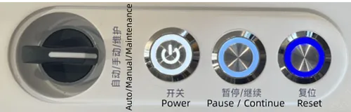
-
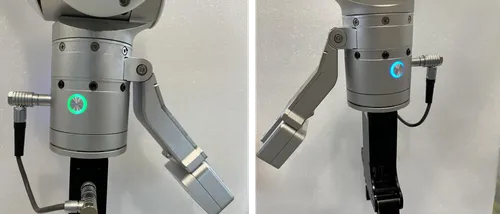
After waiting for 1 minute, the button light at the end of the robotic arm illuminates blue/green, indicating that the robotic arm has been successfully powered on. The robot is then ready for use.
Power Off
Section titled “Power Off”At the chassis, press and hold the Power button for 1.5 seconds to power off the robot. The button light turning completely off indicates that power-off is successful.
Emergency Stop
Section titled “Emergency Stop”If the robot is or may be in a dangerous or abnormal state, immediately press the emergency stop button on the back panel. The robot will stop immediately and enter a safe stopped state.
-
Firmly press the red button on the back panel. An audible “click” indicates that the emergency stop has been triggered.

-
Confirm that the robot is completely stationary, with no motion of the body or end effectors.
-
Check the chassis indicator light. A flashing red light indicates that the emergency stop is active.
-
To resume robot operation, rotate the red button clockwise until it pops out (an audible release sound will be heard).
Charging
Section titled “Charging”When the battery power of AlphaBot 2 is low, it will prompt by voice that charging is needed. AlphaBot 2 provides the following two charging methods; please select the appropriate one according to the specific scenario.
-
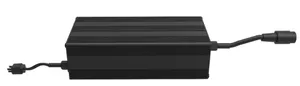
Charging with Power Adapter: After the robot is powered off or switched to manual mode, use the power adapter to directly charge the robot manually.
-
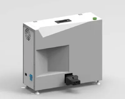
Charging with Charging Box: The robot moves to the charging box by itself for automatic charging.
Before starting the following operations, please read the following safety precautions.
Converting Power Adapter to Charging Box
Section titled “Converting Power Adapter to Charging Box”-
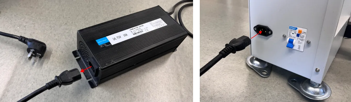
Disconnect the section of the power cable without the transformer from the power adapter, and plug it into the external port on the charging box.
-
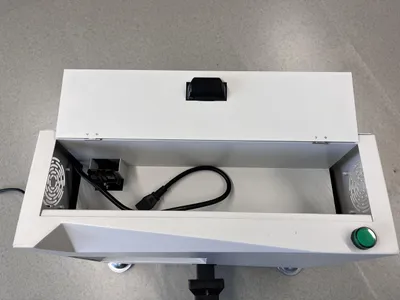
Open the cover on the top of the charging box.
-
Plug the short cable inside the charging box into the transformer, and plug the power cable from the other end of the transformer into the square slot inside the charging box. After completion, close the cover on the top of the charging box.
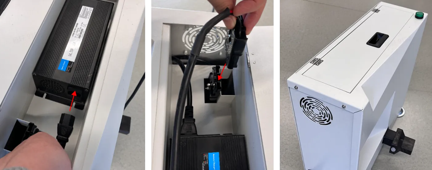
-
When charging, plug the external power cable into the wall outlet. Toggle the circuit breaker on the charging box to the ON position. Verify the status indicator light. If the indicator light shows green, the charging box can be used normally.
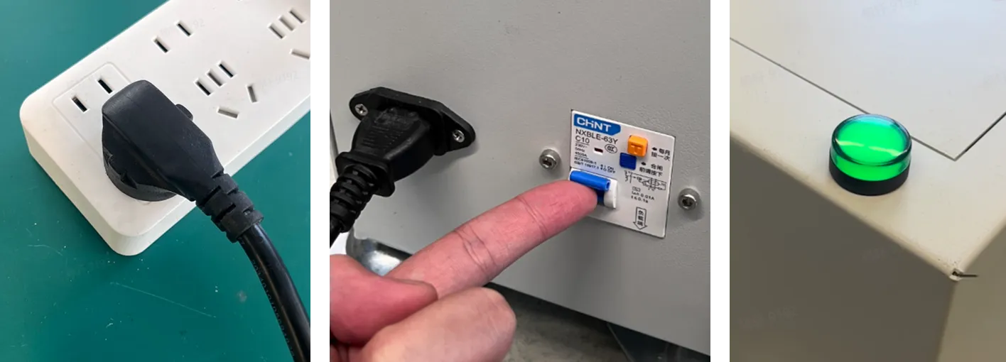
Converting Charging Box to Power Adapter
Section titled “Converting Charging Box to Power Adapter”-
Open the cover on the top of the charging box, unplug the short cable from the transformer, and unplug the power cord at the other end of the transformer from the square slot inside the charging box.
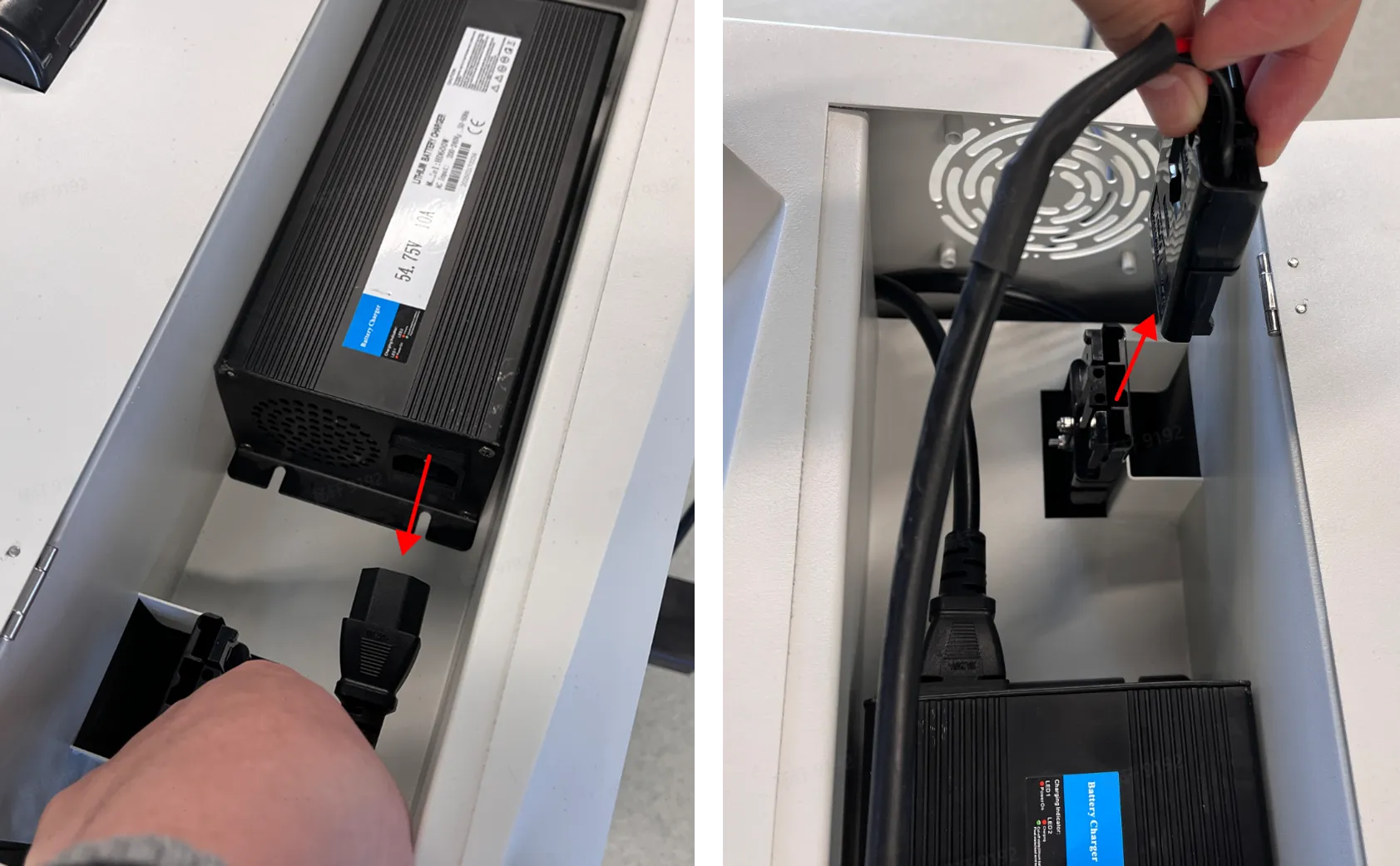
-
Take out the power adapter and close the cover on the top of the charging box.
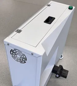
-
Unplug the external power cable from the charging box and plug it into the transformer.
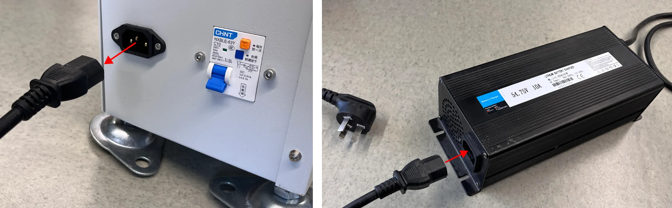
-
Refer to the Charging with Power Adapter section for charging.
Charging with the Power Adapter
Section titled “Charging with the Power Adapter”-
Switch the robot to
Manualmode (or press and hold thePowerbutton for 1.5 seconds to power it off). Then, push the robot to a location near a power socket. -
Connect the power adapter: one end to the power socket, and the other end to the charging interface on the robot chassis. Ensure both ends are firmly connected.
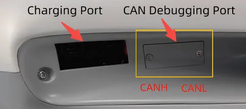
-
After successful connection, the LED2 indicator of the power adapter turns red, indicating that charging is in progress.
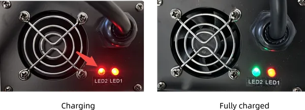
Remote Connection to Main Control Board
Section titled “Remote Connection to Main Control Board”In certain scenarios (e.g., debugging), a computer needs to remotely connect to the main control board via the ssh command. The main control board information is provided in the table below.
| Item | Description |
|---|---|
| Main Control Module | NVIDIA AGX Orin 64G |
| Username | robot |
| IP Address | 192.168.90.1 |
| Wi-Fi SSID (Name) | Format: Alphabot2-xxx-xxxx. Refer to the delivery checklist for the specific value. |
| Wi-Fi Default Password | 88888888 |
The following procedure uses the Windows operating system as an example to detail how to connect a computer to the main control board.
-
Click on the wireless network icon. Locate the Wi-Fi network name in the format
Alphabot2-xxx-xxxx, then clickConnect. This example uses Alphabot2-088-5d50.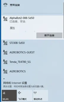
-
In the search box, search for
Network Connectionsand clickView network connections.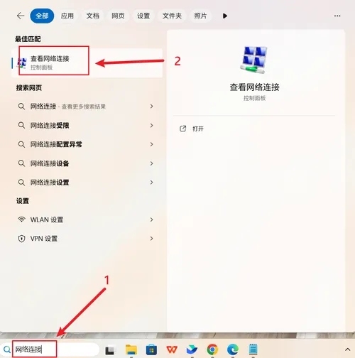
-
Double-click
Alphabot2-xxx-xxxx, then clickDetails. Locate the IPv4 default gateway address. This address is the IP address used to remotely log into the main control board.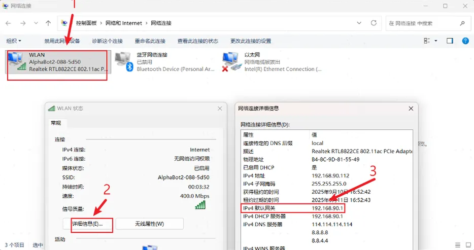
-
Press the
Win+Xshortcut keys to open the menu, then clickTerminal.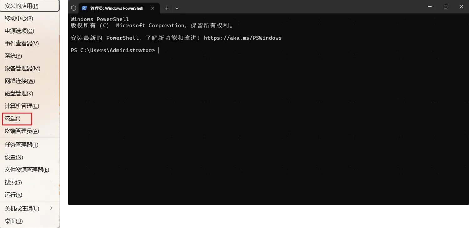
-
In the terminal, enter the
ping 192.168.90.1command. A display as shown in the figure below indicates that login operations can proceed.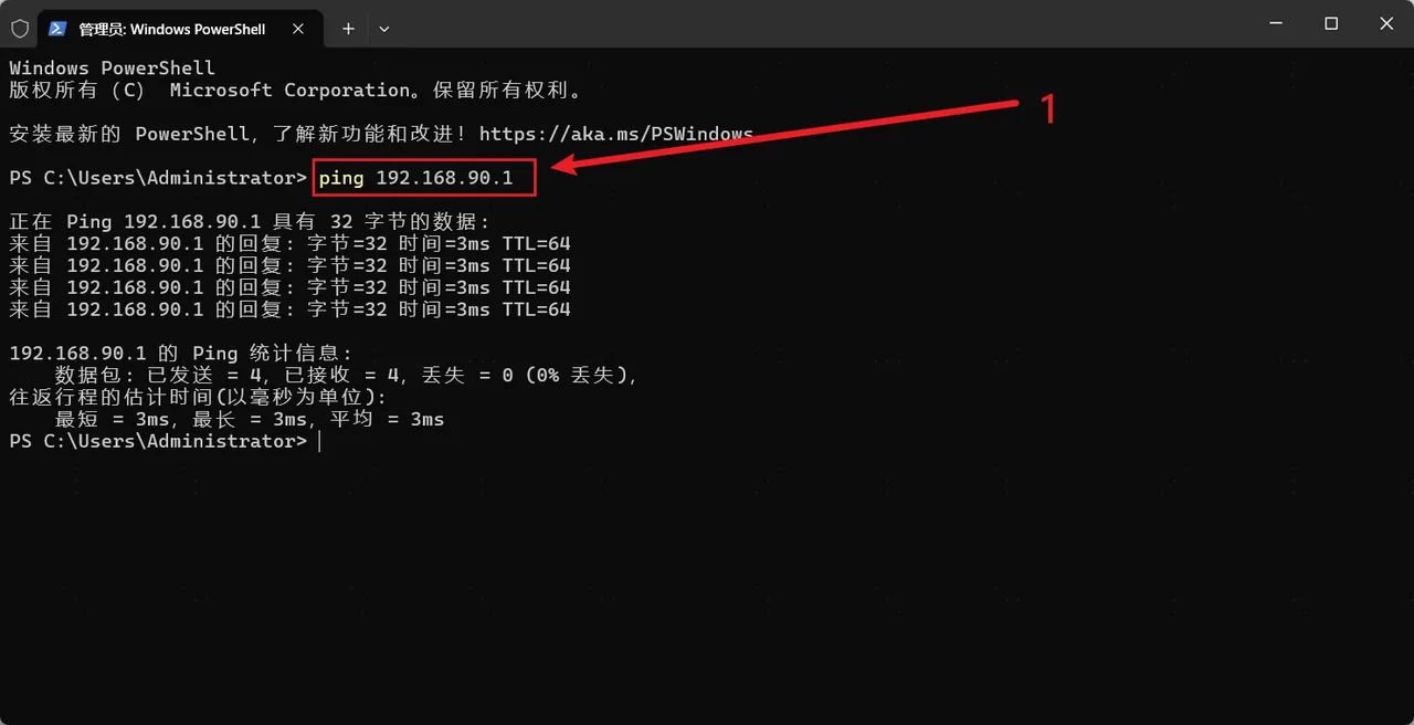
-
In the terminal, enter the
ssh robot@192.168.90.1command. Then enteryesand the login password (the default password is88888888). A display as shown in the figure below indicates a successful connection to the main control board.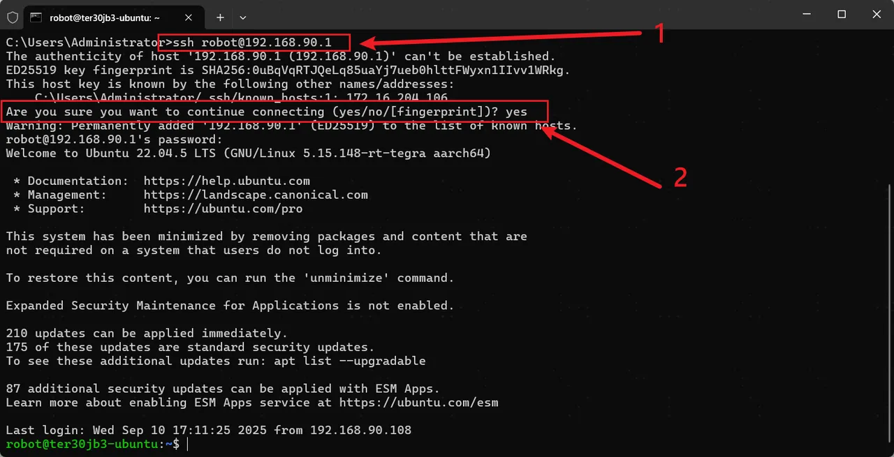
If you need to configure Wi-Fi connection, please continue with the following operations.
-
In the same terminal from the previous step, continue by entering the
sudo nmcli device wifi listcommand to view available Wi-Fi networks. Record the SSID (name) of the Wi-Fi network to connect to.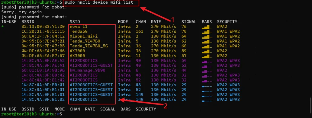
-
In the same terminal, continue by entering the
sudo nmcli device wifi connect <SSID> password <password>command to connect to the new Wi-Fi network. Replace<SSID>and<password>with the SSID and password of the target Wi-Fi network, respectively.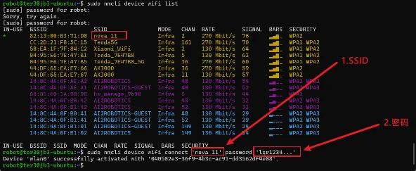
-
Enter the
ifconfigcommand to view the IP address assigned by the wireless network to the main control board (i.e., the wlan0/wlp2s0 IP address) to check and confirm whether it has been successfully connected to the specified Wi-Fi network. So far, the Wi-Fi configuration is completed.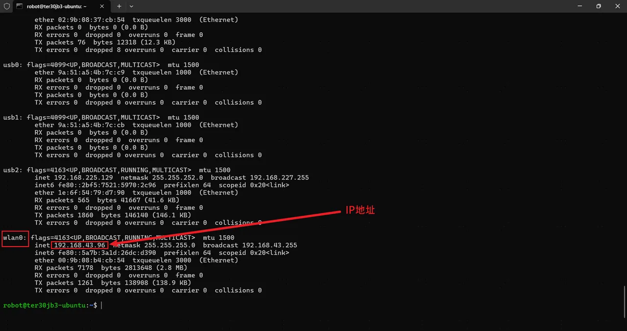
-
After completing the Wi-Fi configuration, connect the computer to the above Wi-Fi, then enter the command
ssh robot@x.x.x.xin the terminal, wherex.x.x.xis the IP address obtained in the previous step, then enteryesand the login password to log in successfully. There is no need to reconfigure Wi-Fi every time you connect to the main control board.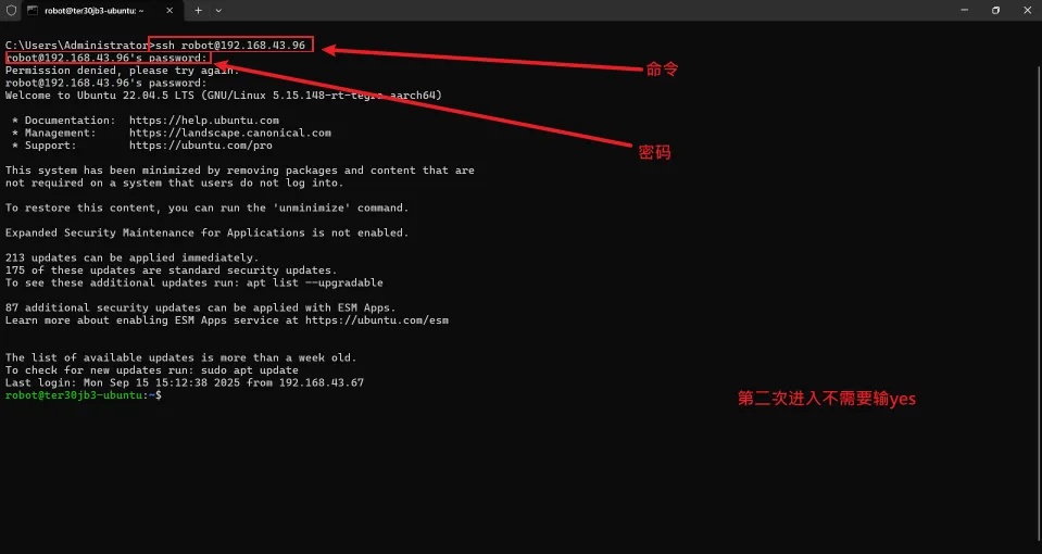
Operating Chassis Upper Computer Software
Section titled “Operating Chassis Upper Computer Software”AlphaBot 2 provides two types of chassis upper computer software. The following table contains information about the two software applications; please select the appropriate one according to the actual usage scenario.
| Software Name | Applicable Platform | Description |
|---|---|---|
| AI2ROBOTICS Design | Windows Computer | It has three major functions: map editing, task editing and monitoring information, which is convenient for operators to flexibly monitor and manage robots in multi-machine working scenarios. |
| AI2ROBOTICS Mobile | Android Tablet | It integrates functions such as real-time monitoring and control, task planning, device configuration, and map construction, making it convenient for operators to better monitor and manage robots in mobile scenarios. |
AI2ROBOTICS Design
Section titled “AI2ROBOTICS Design”Follow the steps below to quickly master the use of the AI2ROBOTICS Design software.
-
Open the AI2ROBOTICS Design software to enter the home screen. Click the Settings icon in the lower-left corner, then select
Connect.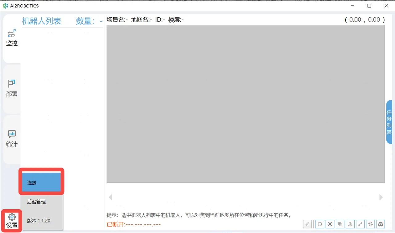
-
In the pop-up window, enter the IP address and port number of the chassis, then click
Connect. After a successful connection, the bottom status bar will indicate “Connected” and display the connected IP address.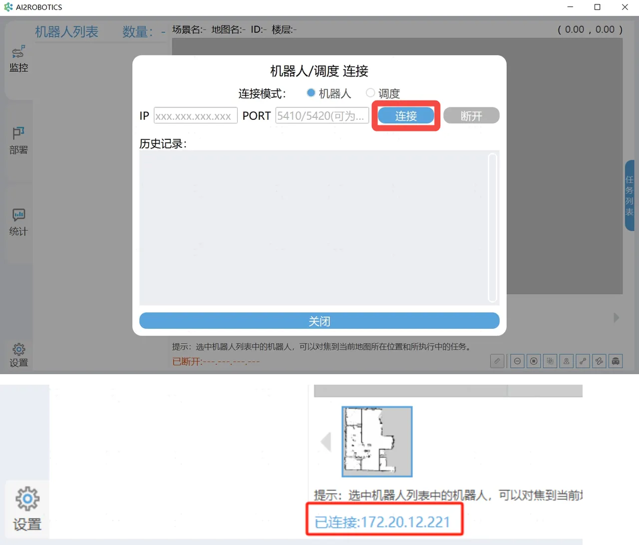
-
After a successful connection, click
Monitoringin the left navigation bar to view the current status information of the chassis. -
Click
Deploymentin the left navigation bar to enter the deployment interface.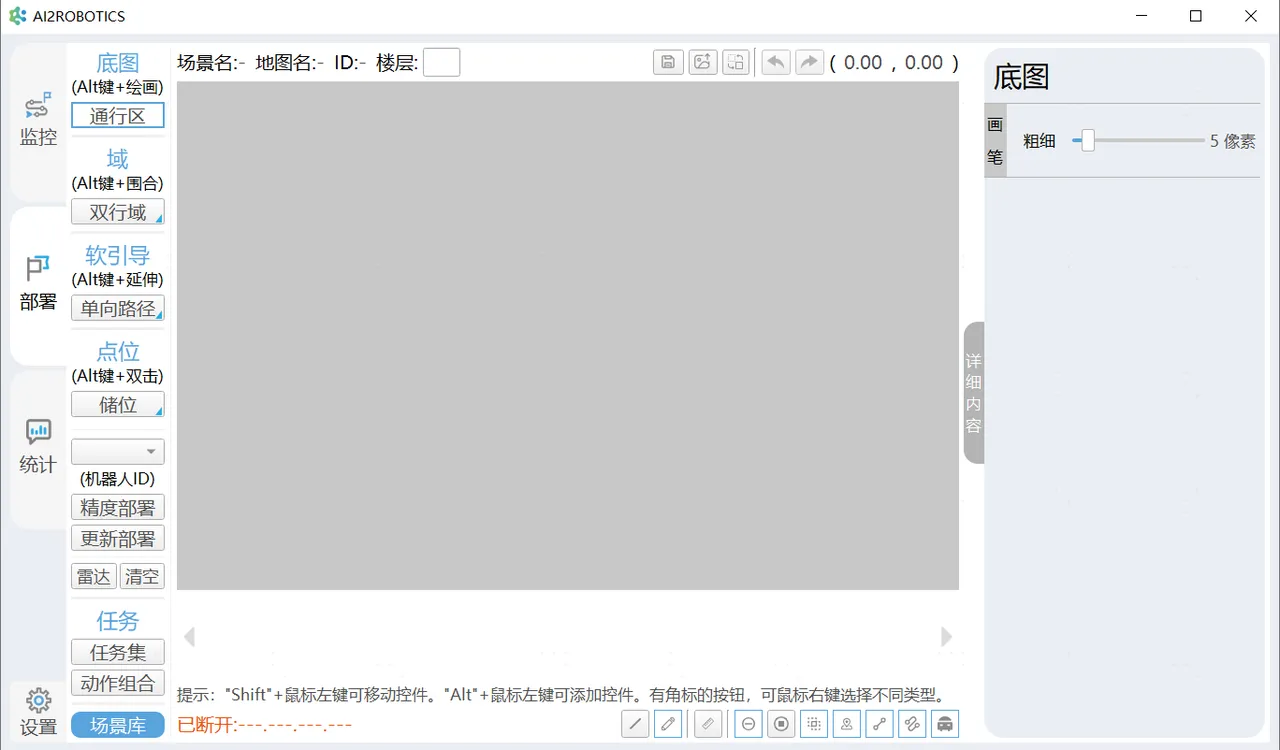
Option Description Map Editing Click to enter the map editing page to edit the physical walls, passage areas, navigation restricted areas, and traffic control restricted areas of the map. Field Editing Edit some common domains to restrict some behaviors and rules of the robot in this area. Soft Guide Editing Restrict the behaviors and rules of the robot’s walking path. Waypoint Editing Edit some navigation target points and task target points, including transportation, lifting and handling, charging piles, parking points, etc. Task Editing Edit some task sets according to the deployed points and action groups, such as cycle tasks, timeout waiting tasks, temporary tasks, etc. Scene Library Load map scenes for task editing and deployment. -
Click
Statisticsin the left navigation bar to view statistical information.
AI2ROBOTICS Mobile
Section titled “AI2ROBOTICS Mobile”Follow the steps below to quickly master the use of the AI2ROBOTICS Mobile software.
-
Navigate to the Wi-Fi connection interface of the tablet system. Connect to the robot hotspot
AI2Rocks-xxxx(wherexxxxis the serial number). Enter the default password88888888. If already connected to the robot hotspot, this step may be skipped. -
Open the AI2ROBOTICS Mobile software to enter the home page. Click
Ununited. Enter the chassis fixed IP address169.254.128.2and clickConnect.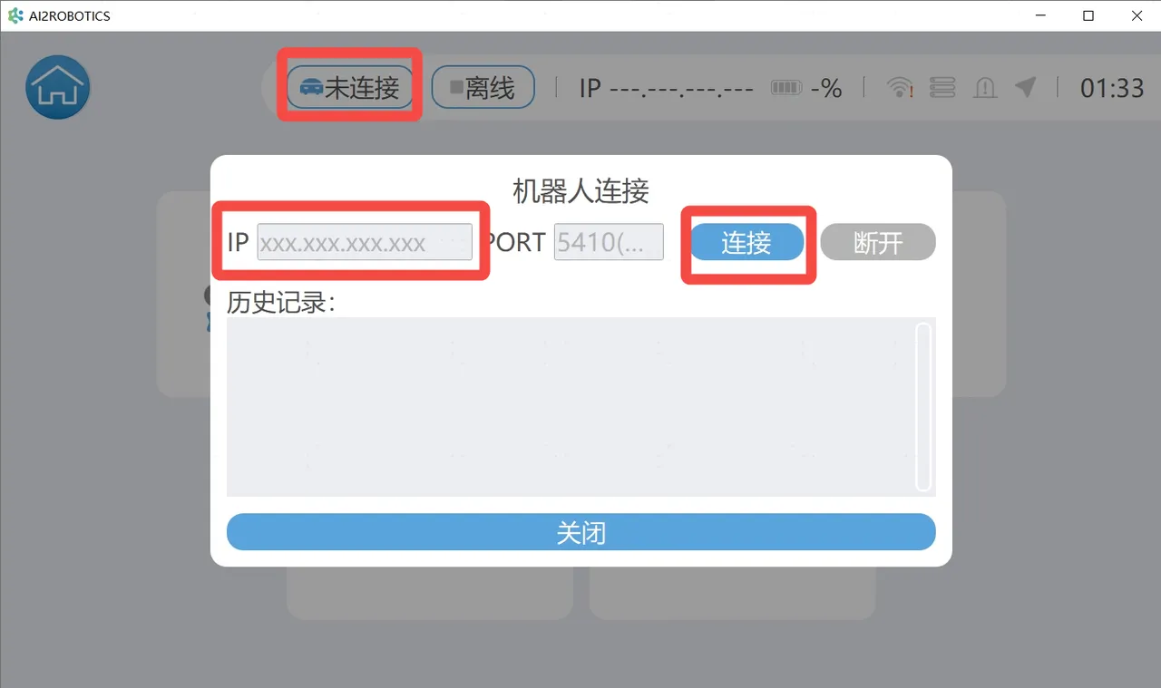
-
After successful connection, on the home page, you can select options such as Monitor, Map, Task, Settings, and Device to operate.
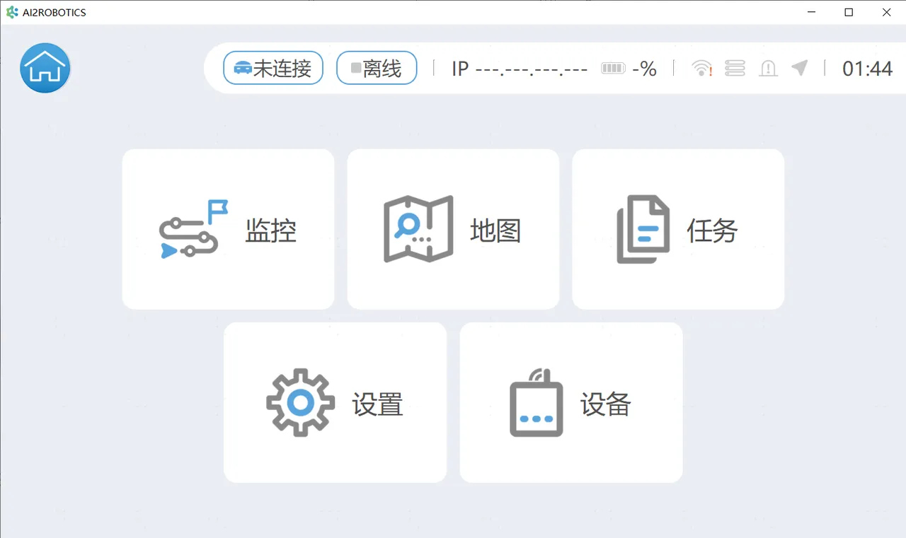
Option Description MonitorView the navigation map information currently used by the connected robot. Map View all navigation map information of the currently connected robot. Task Edit some task sets according to the deployed points and action groups, such as cycle tasks, timeout waiting tasks, temporary tasks, etc. Settings Modify information and remotely control the robot’s movement. Device View robot status, current and other information.
Using the Robotic Arm Teach Pendant
Section titled “Using the Robotic Arm Teach Pendant”AlphaBot 2 provides a web-based robotic arm teach pendant software. You can enter the URL in a browser to access the teaching interface, operate the robotic arm and controller, and view related information.
Follow the steps below to quickly master the use of the robotic arm web teach pendant software.
-
Open a browser, enter
192.168.1.18(left arm) or192.168.1.19(right arm), and pressEnterto access the login page.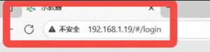
-
On the login page, enter the username
userand password123, then clickLogin.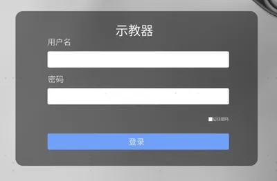
-
Click
Robotic Arm Teach Pendantin the left navigation bar to enter the teaching interface, where you can perform teaching operations.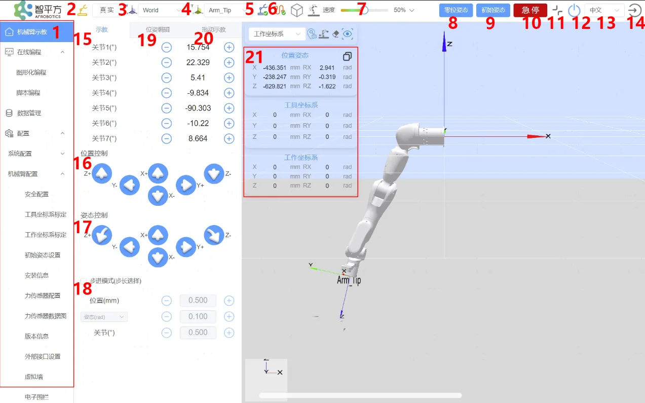
No. Option Description 1Menu Bar OptionsUsed to switch functions such as Robotic Arm Teach Pendant, Programming, Data Management, Configuration, System Information, and Extension. 2 Work Mode The yellow icon represents the selection of real mode, where the program runs on the actual robot. The gray icon represents the selection of simulation mode, where the actual robot does not move, and only the 3D simulation model is operated. 3 Work Frame Allows selection of the work frame to control the robotic arm motion state. 4 Tool Frame By default, the displayed pose target is the flange center. You can set your own tool frame. 5 Robotic Arm State When an error occurs in the robotic arm, it will be indicated here. Clicking the icon will open the error message list. 6 Network Connection State When the connection to the robotic arm is normal, it turns green; when communication is disconnected, it turns red. 7 Speed You can either display in real-time or adjust the robotic arm movement speed as a percentage of its maximum speed using the slider. 8 Zero Pose Long press the Zero Posebutton to move the robotic arm back to its zero position. Releasing the button stops the motion.9 Initial Pose Long press the Initial Posebutton to return the robotic arm to its initial position.10 Stop Pressing the Stopbutton stops the robot at maximum speed. Pressing it again cancels the emergency stop, allowing the robotic arm to be operated again.11 Full Screen This button is used to control entering and exiting full-screen mode on the teaching interface. 12 Power This button is used to control the robotic arm power switch. Blue indicates that the robotic arm power is on, and gray indicates that the robotic arm power is off. 13 Switch Language Click the language switch dropdown menu and select the target language to switch to it. 14 Logout Clicking the logout button logs the user out. 15 Joint Control Use the joint control buttons on the teaching interface to control the rotation of each joint. 16 Position Control You can perform teaching for the end effector under different frames. 17 Pose Control You can perform teaching for the end effector under different frames. During orientation teaching, the end position remains unchanged, while the orientation rotates around a specified coordinate axis. 18 Step Mode To improve teaching accuracy, the step control mode is used, allowing controlled variables to change accurately with step adjustments. 19 Pose Editing Allows editing of the robotic arm motion pose. Long press the Apply button to move the robotic arm to the position of the red virtual model; releasing the button stops the robotic arm. 20 Drag Teaching On the teach pendant, click the Drag teachingbutton, and then drag the robot. Once completed, clickend the drag teachingto complete the trajectory recording. After the trajectory recording is completed, click the blue button at the end of the robot to replay the trajectory.21 End-effector Pose Parameter Displays the end-effector pose parameters, including position coordinates and Euler angles. -
Click
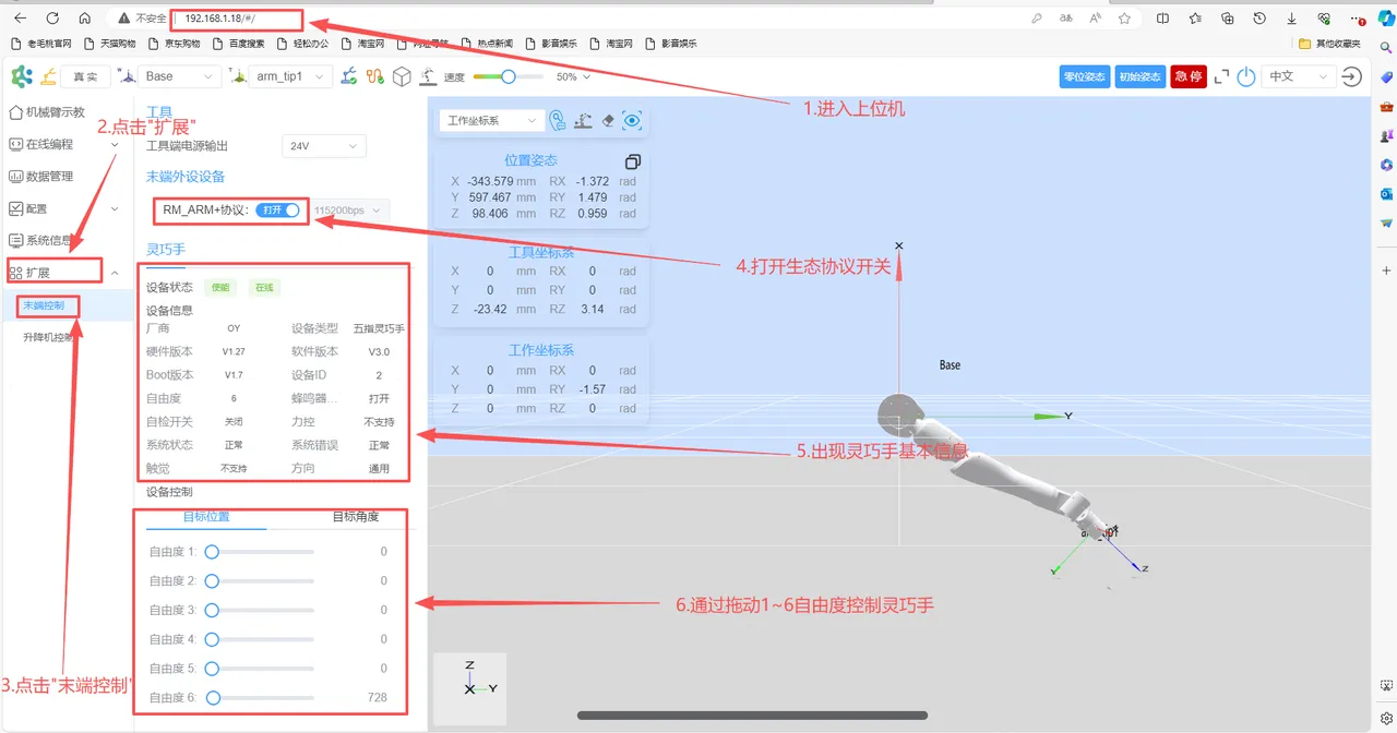
Extension -> End Controlin the left navigation bar to configure the end-effector tools.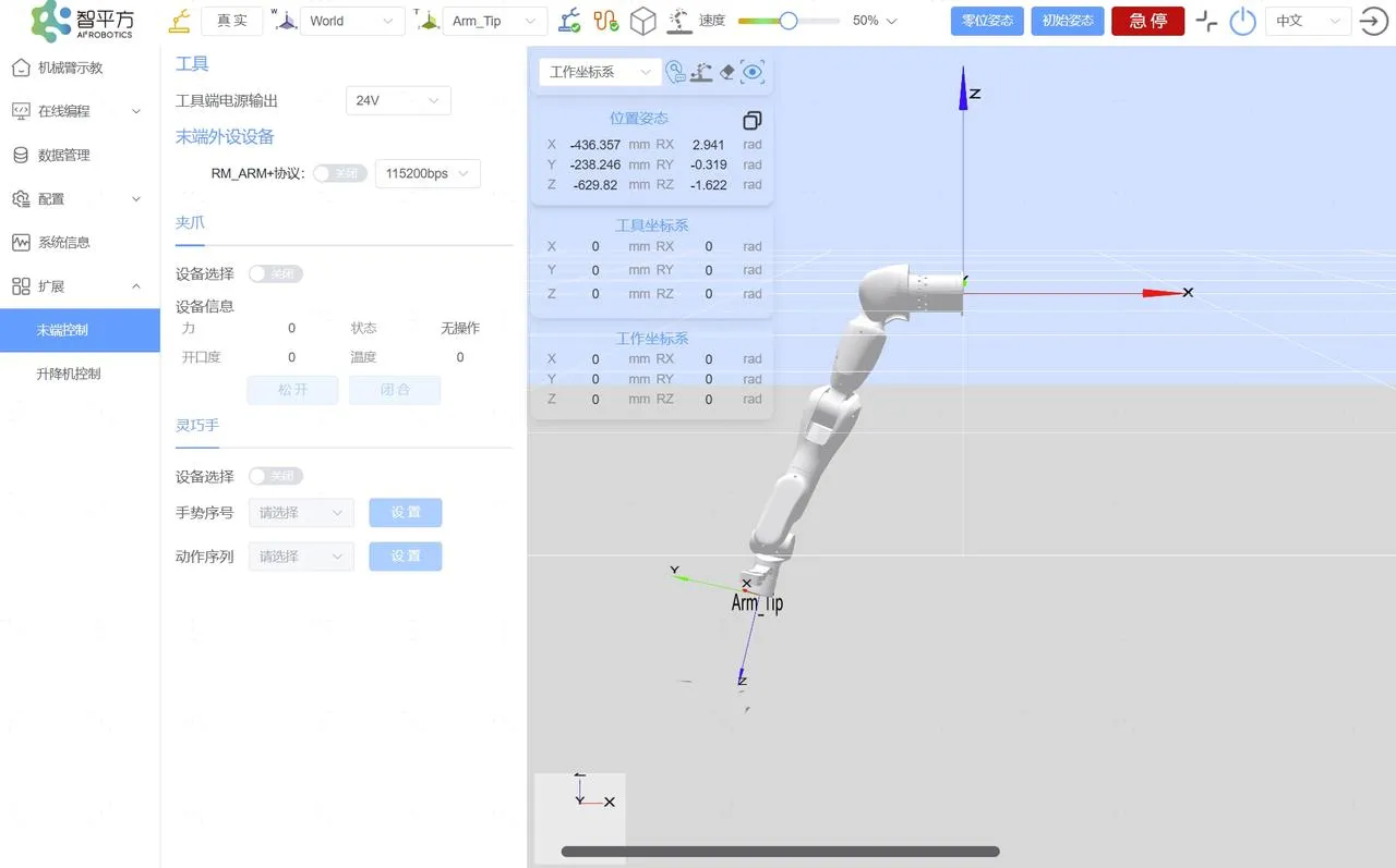
Option Description Tool Power Supply Output Configures the output power from the tool end interface board. Options: 0V, 5V, 12V, and 24V. End-Effector Peripheral Devices Currently, only grippers and dexterous hands are supported; support for other devices can be added later.
Debugging the Chassis CAN Interface
Section titled “Debugging the Chassis CAN Interface”The AlphaBot 2 chassis is equipped with a CAN debugging interface, which is used by our engineers for maintenance when the motor malfunctions. Do not debug it without authorization.
Firmware Upgrade
Section titled “Firmware Upgrade”Upgrading Robotic Arm Firmware
Section titled “Upgrading Robotic Arm Firmware”-
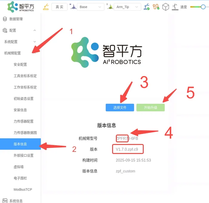
Refer to Using the Robotic Arm Teach Pendant and log in to the robotic arm web teach pendant interface using the IP address
192.168.1.18(left arm) or192.168.1.19(right arm). -
Follow the steps in the figure below to select the firmware file and perform the upgrade.
-
Wait for a moment. After the upgrade is completed, the robotic arm will make a “beep beep beep” sound. After the upgrade is completed, please restart the robotic arm to make the new firmware take effect.
-
After the robotic arm restarts, open the web teach pendant. After entering the home page of the teach pendant, press Ctrl+F5 to force refresh the browser and clear the cache. At this time, the robotic arm and web teach pendant can be used normally.
Updating Robotic Arm End-Effector Controller Firmware
Section titled “Updating Robotic Arm End-Effector Controller Firmware”-
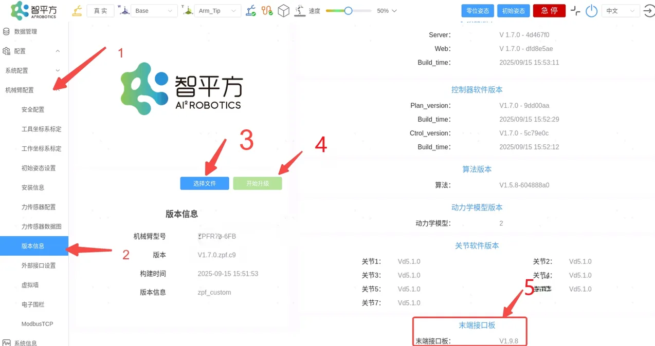
Refer to Using the Robotic Arm Teach Pendant and log in to the robotic arm web teach pendant interface using the IP address
192.168.1.18(left arm) or192.168.1.19(right arm). -
Follow the steps in the figure below to select the firmware file (tool.bin file) and perform the upgrade. After the upgrade is completed, please restart the robotic arm, open the web teach pendant, and press Ctrl+F5 to force refresh the browser. At this time, the version number of the End-Effector interface board has been updated.
Updating Inspire Gripper Firmware
Section titled “Updating Inspire Gripper Firmware”-
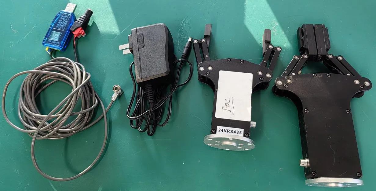
Prepare the following items: gripper (large gripper or small gripper), power cable, data cable, computer (Windows operating system), firmware file, and the Inspire Drive Firmware Update Tool.
-
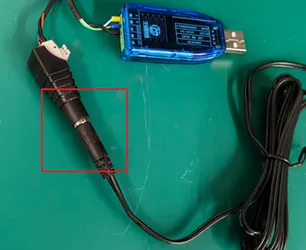
Connect one end of the power cable to the data cable, and connect the other end of the power cable to the power supply.
-
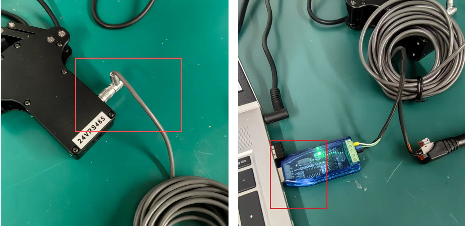
Connect one end of the data cable to the gripper, and connect the other end of the data cable to the USB port of the computer.
-
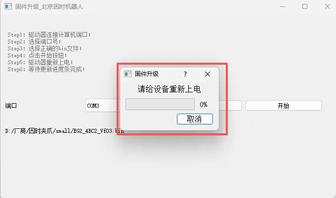
Open the Inspire Drive Firmware Update Tool (.exe file). Select the firmware file (.bin file) corresponding to the gripper. Click
Start.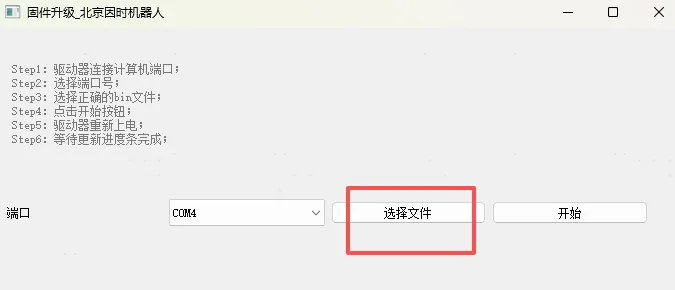
-
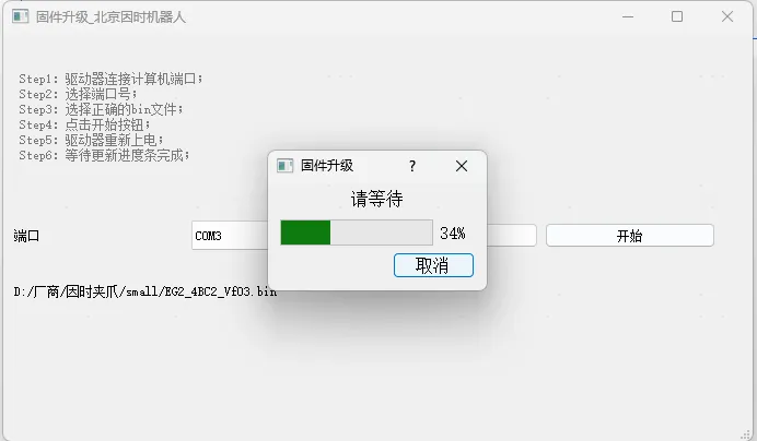
When the following prompt appears, re-plug the power cable. Wait for the progress bar to complete.
-
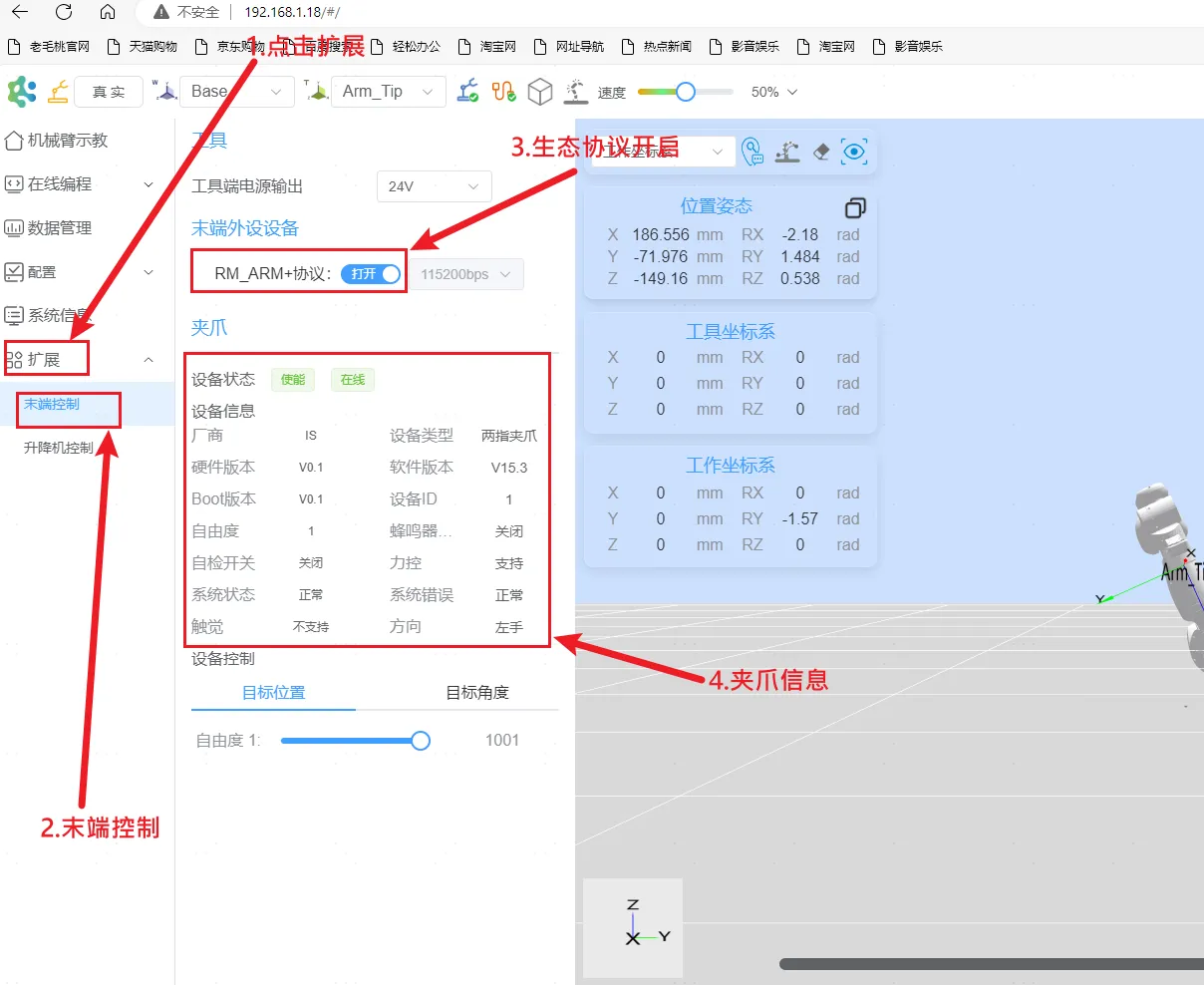
Configure the tool power supply output to the voltage corresponding to the gripper, enable the RM_ARM+ protocol, and the gripper information will appear.
-
Under
Target Position, drag DOF 1 to control gripper closing and opening.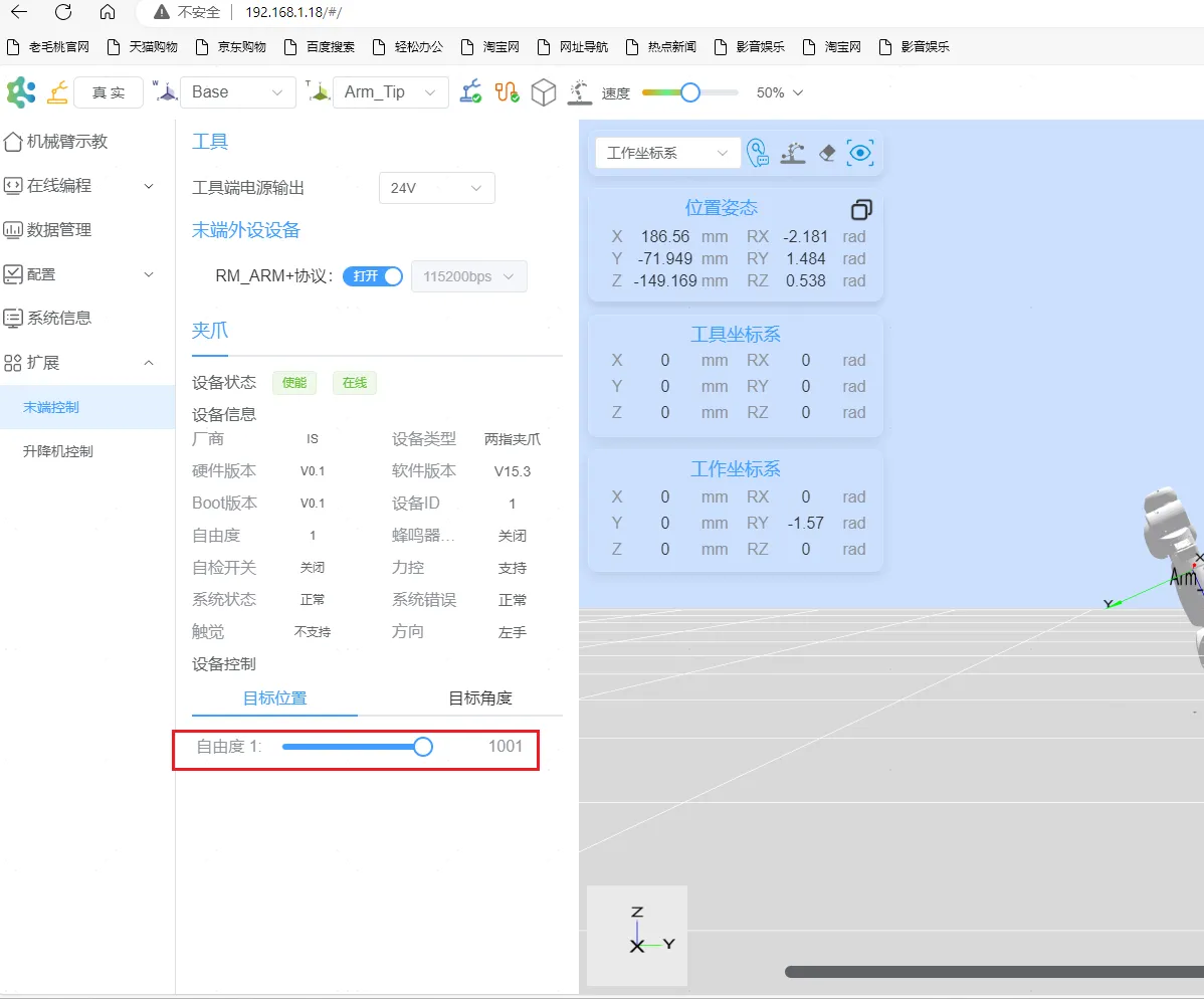
Updating OYMotion Dexterous Hand Firmware
Section titled “Updating OYMotion Dexterous Hand Firmware”-
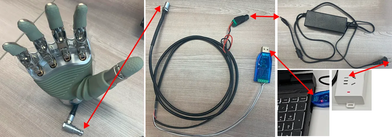
Prepare the following items: dexterous hand, power cable, data cable, computer (Windows operating system), firmware file, and the OYMotion software (requires download and installation).
-
Refer to the figure below to connect all components.
-
Open the OYMotion software. Navigate to the
Basicinterface. Click theUpdatebutton to enter firmware upgrade mode. SelectLocalas the firmware source, clickOK, and then select the firmware file (.upd file).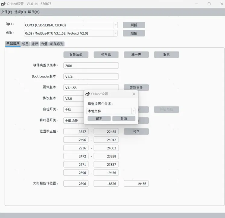
-
Follow the software interface prompts to complete the firmware upgrade. After the upgrade is complete, the dexterous hand will reboot and perform a self-check. At this point, scan for the device again. The device information will be reloaded.
-
In the robotic arm web teach pendant interface, click
Extension -> End Control. Configure the tool power supply output to the voltage corresponding to the dexterous hand, enable the RM_ARM+ protocol, and the dexterous hand information will appear. UnderTarget Position, drag DOF 1 through DOF 6 to control the motion of the dexterous hand.