

Common Operations
Mastering the following operations will help you use the Exoskeleton Teleoperation Device more efficiently.
Starting the HMI Interface
Section titled “Starting the HMI Interface”ROBOT-CONTROL-HMI (hereinafter referred to as HMI) is the graphical user interface for controlling and monitoring the robot system. It serves as the core tool for interacting with the robot when using the Exoskeleton Teleoperation Device. The HMI consists of two separate programs: the user-side program and the robot-side program. Both must be started before use, following the procedures below.
Starting the User-Side Program
Section titled “Starting the User-Side Program”-
Check that Microsoft Edge is installed and set as the default browser.
-
On the industrial PC, open a terminal and enter the following commands.
Terminal window cd ~bash ~/user_docker_start.sh -
After the script executes, the Microsoft Edge browser will launch the HMI interface automatically. If it does not open automatically, manually enter
http://127.0.0.1:4090in the browser’s address bar.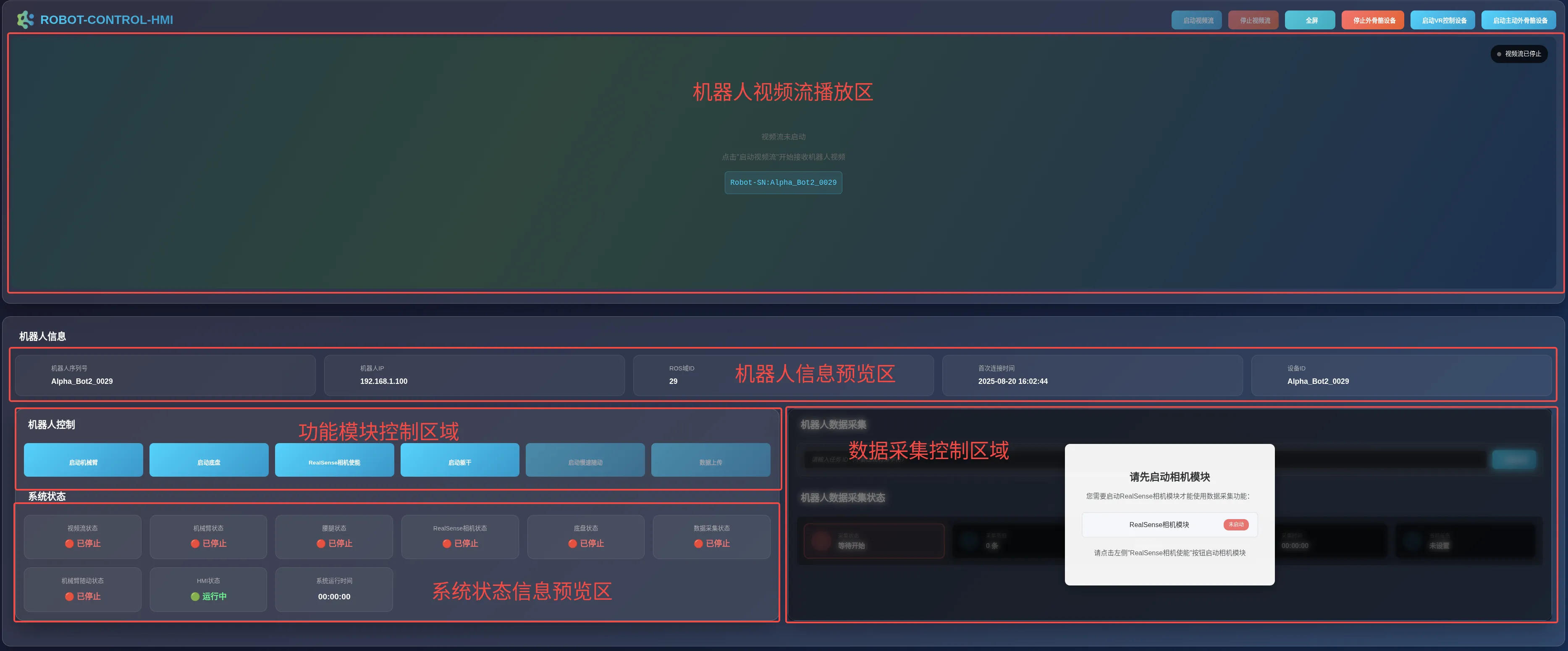
Starting the Robot-Side Program
Section titled “Starting the Robot-Side Program”-
On the industrial PC, open a new terminal window and remotely connect to the robot terminal using the
sshcommand.Terminal window ssh <username>@<robot_IP_address> -
In the successfully connected terminal, enter the following commands.
Terminal window cd ~bash ~/robot_docker_start.sh
After Starting the HMI interface, you can use the exoskeleton device to control the robot.
Using the Exoskeleton Device
Section titled “Using the Exoskeleton Device”Starting the Exoskeleton Control Device
Section titled “Starting the Exoskeleton Control Device”-
After starting the HMI interface, click the
Start Exoskeleton Devicebutton. Once started successfully, the button will turn red and the text will change toStop Exoskeleton Device.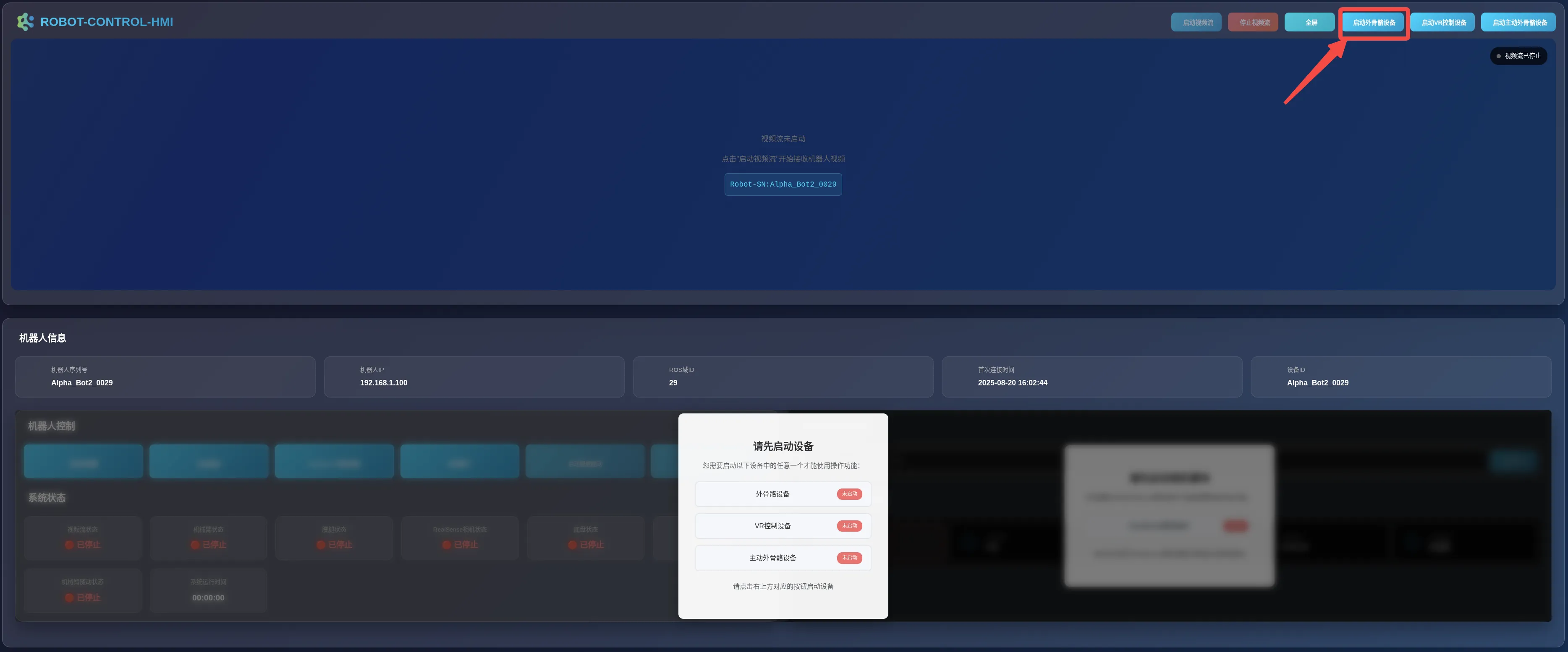
-
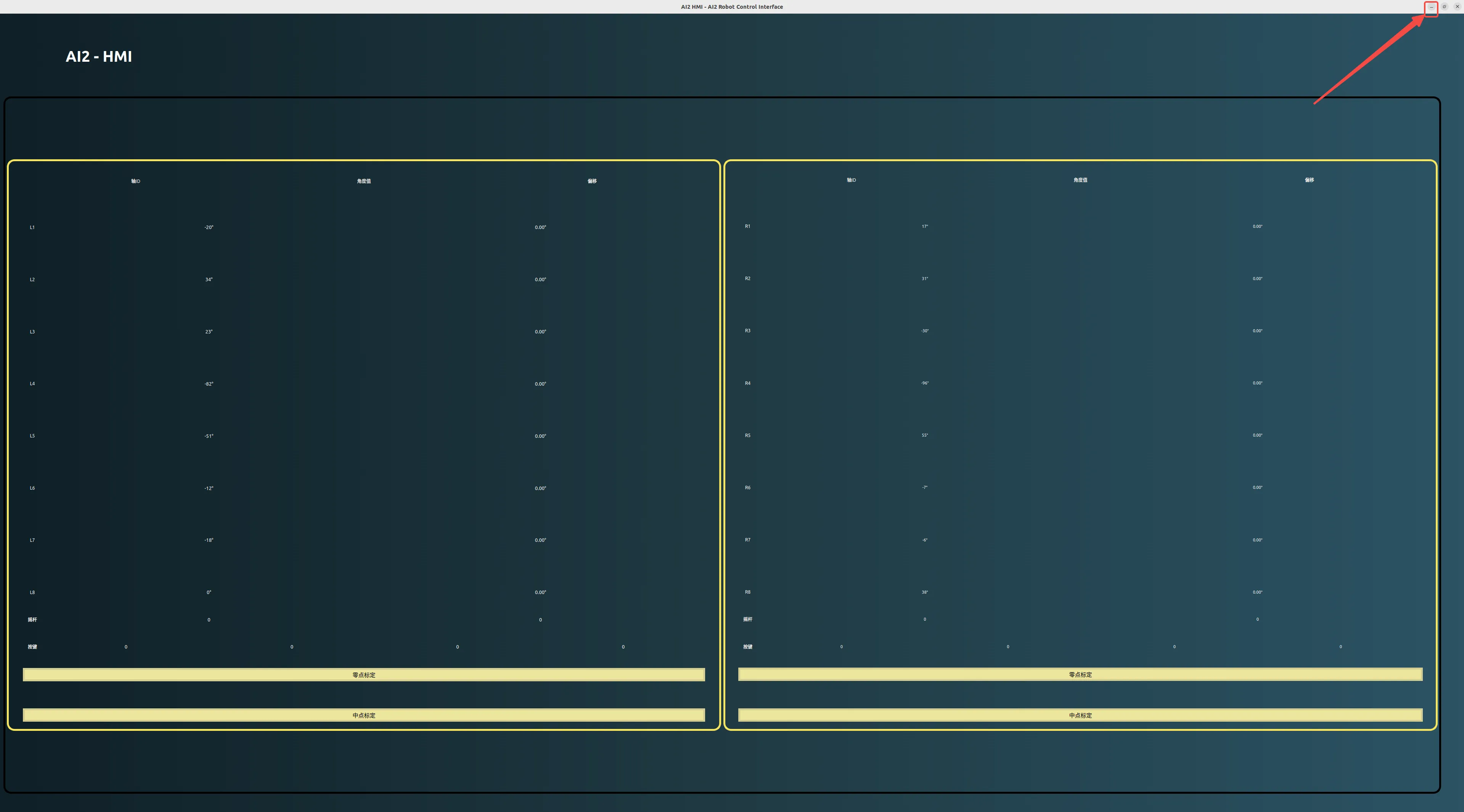
The AI2-HMI window will pop up. This window displays real-time teleoperation data. Do not close this window during operation.
Starting the Camera and the Video Stream
Section titled “Starting the Camera and the Video Stream”-
After ensuring that the Exoskeleton Device has been successfully started, click the
Start RealSense Camerabutton in theRobot Controlpanel.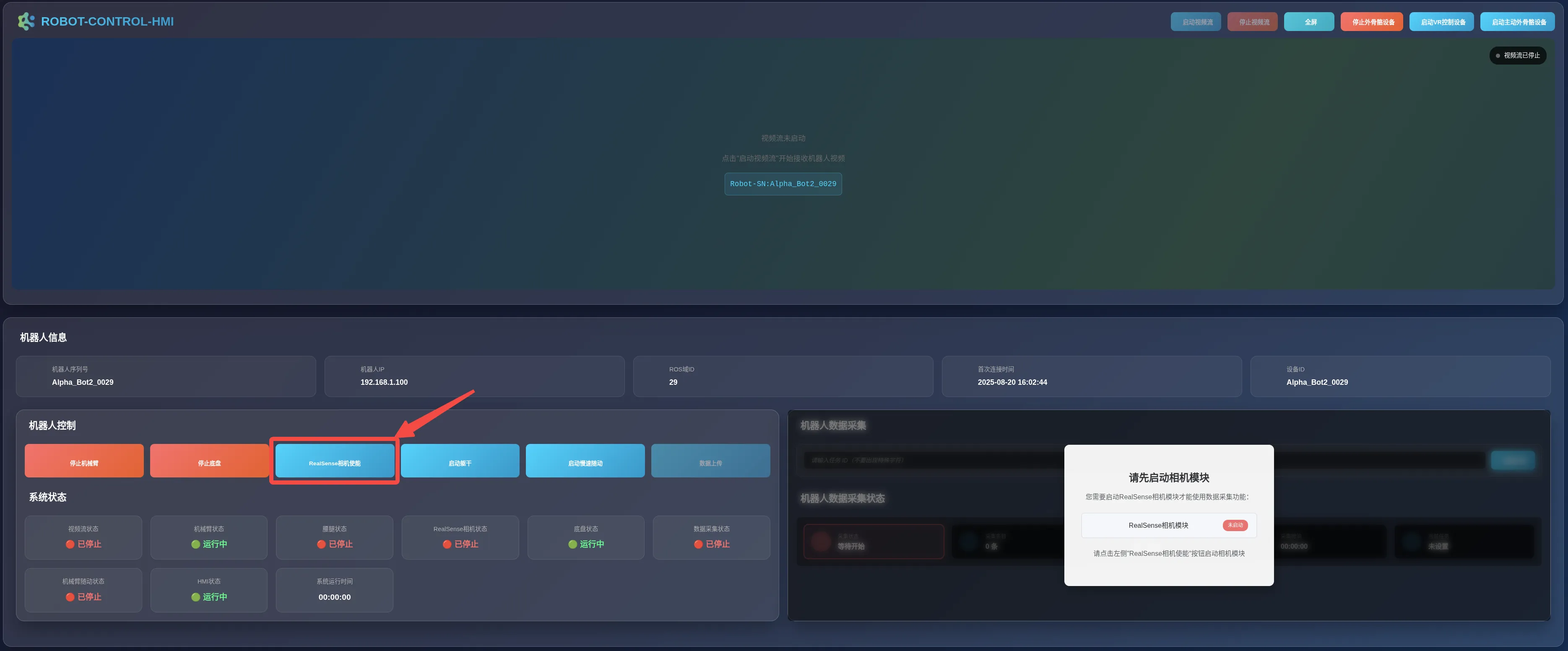
-
A prompt message as shown below will appear; please wait patiently.
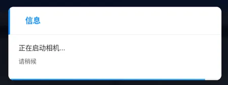
-
Upon successful startup, the RealSense camera will enter a self-check state. The
Start RealSense Camerablue button will change to a redStop RealSense Camerabutton, and theRealSense Camera Statusin theSystem Statuspanel will displayRunning.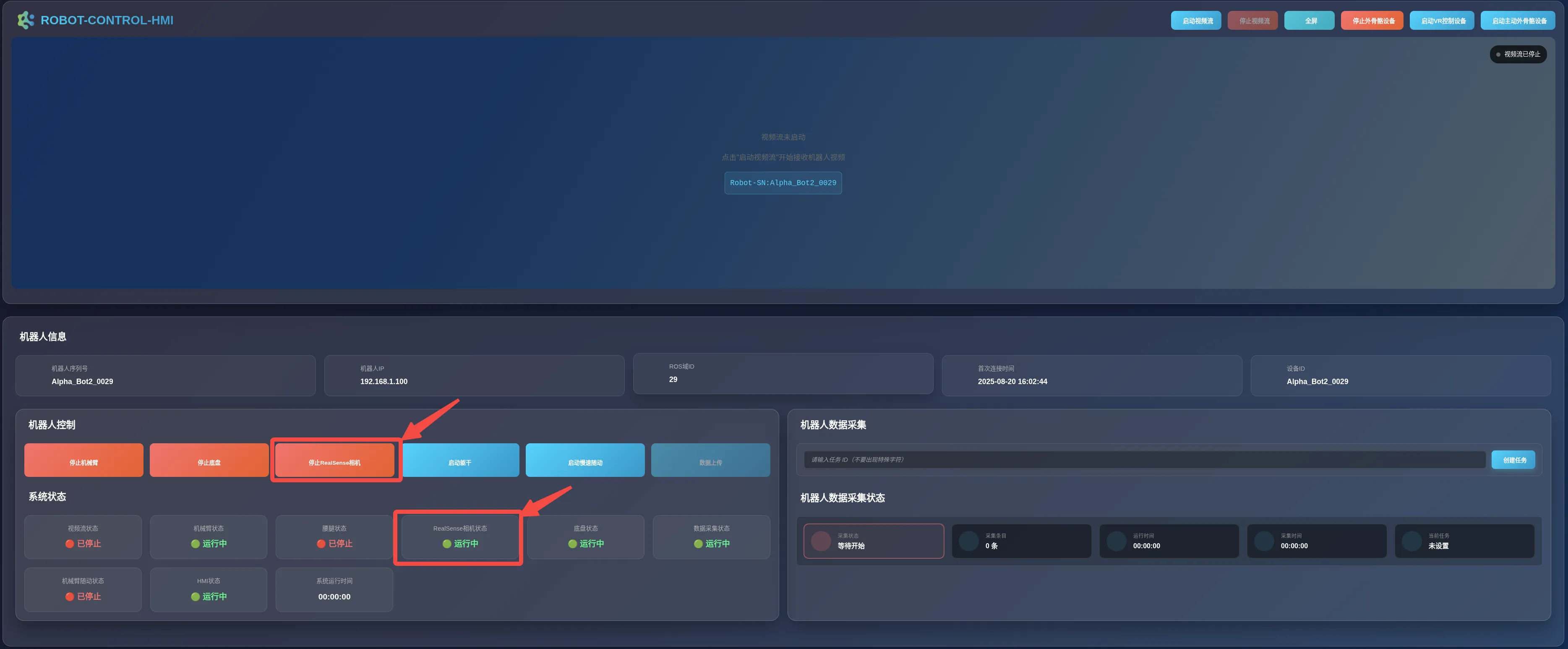
-
Click the
Start Video Streambutton in the upper-right corner of the interface.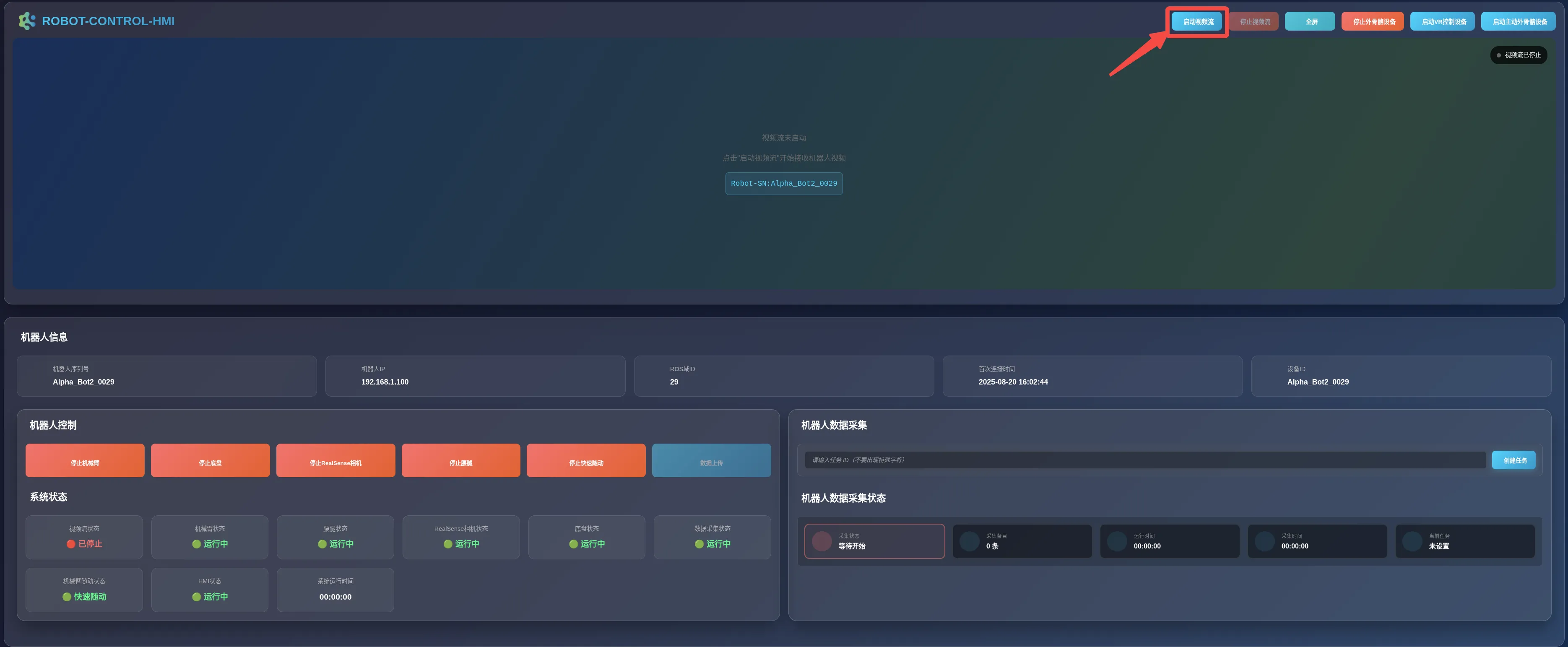
-
A window as shown below will pop up. This window will close automatically.
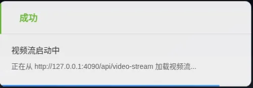
-
The video stream playback area will display the real-time video stream, and the
Video Stream Statusin theSystem Statuspanel will displayRunning.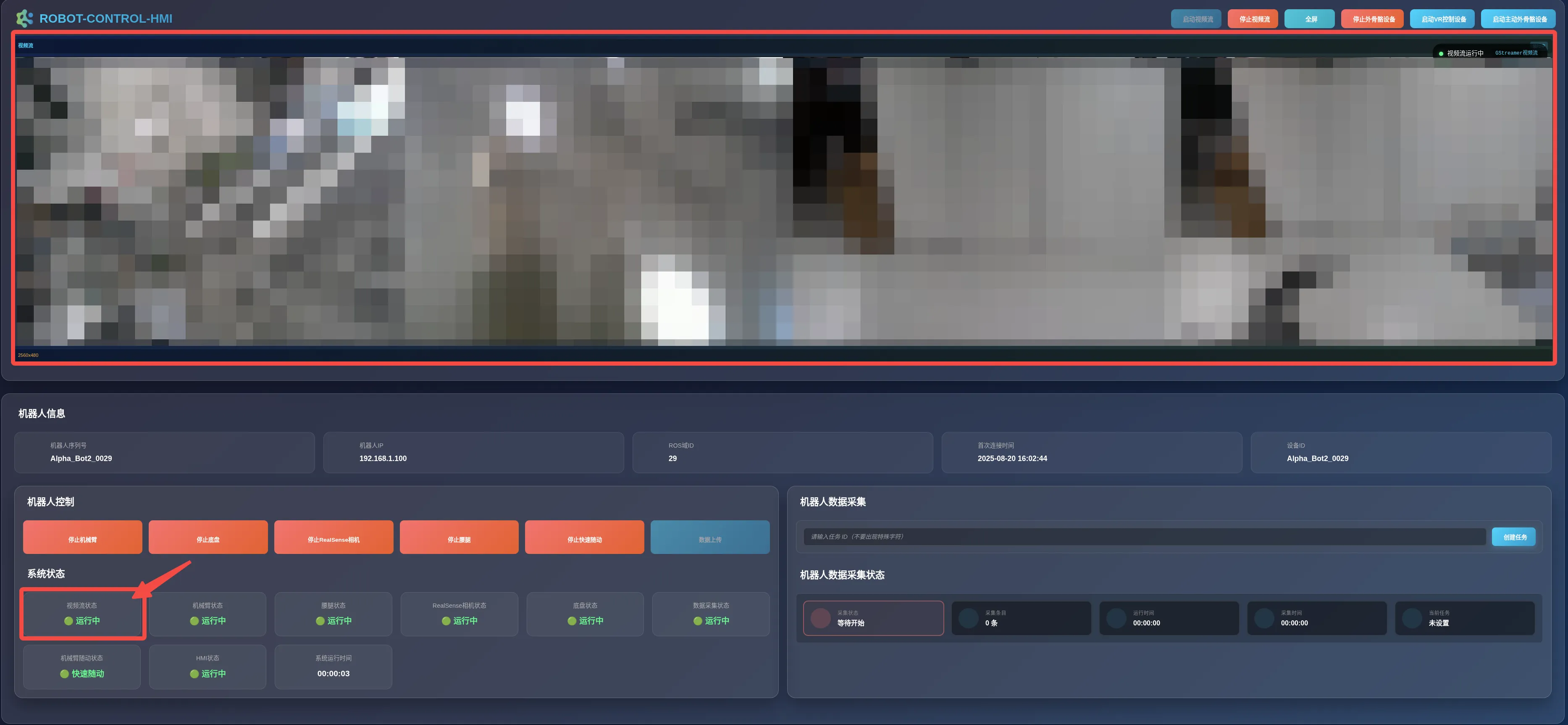
Starting the Robotic Arm
Section titled “Starting the Robotic Arm”-
After ensuring that the camera and the video stream have been successfully started, click the
Start Robotic Armbutton in theRobot Controlpanel.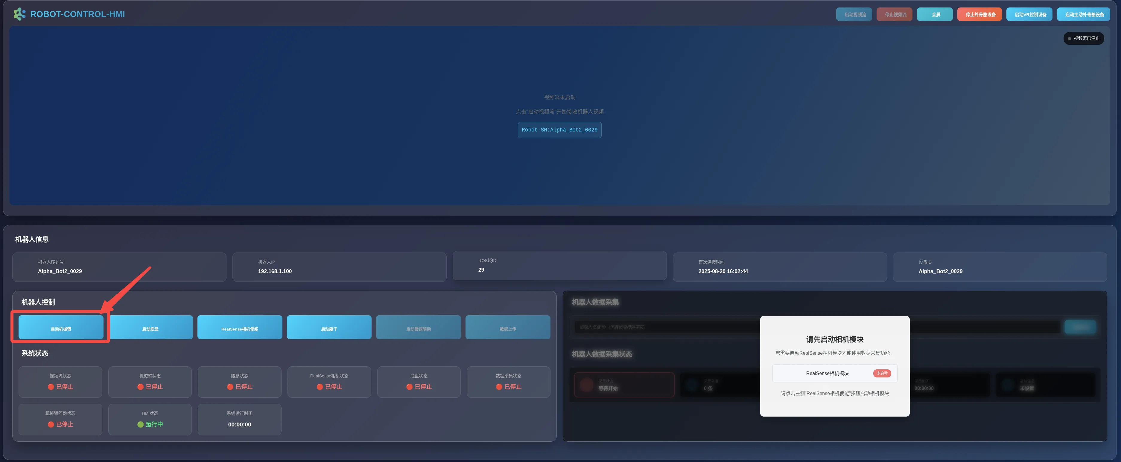
-
A prompt message as shown below will appear; please wait patiently.
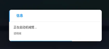
-
Upon successful startup, the robotic arm will enter a self-check state. The
Start Robotic Armblue button will change to a redStop Robotic Armbutton, and theRobotic Arm Statusin theSystem Statuspanel will displayRunning.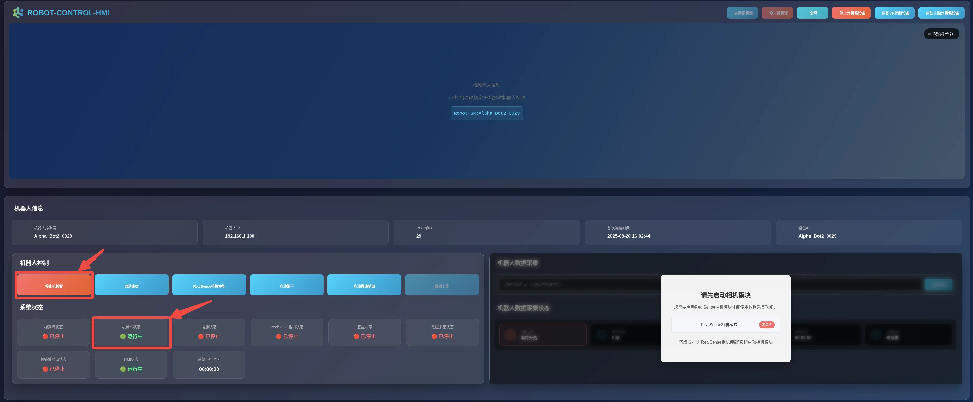
Starting Follow-Up
Section titled “Starting Follow-Up”-
After ensuring the robotic arm has been started, click the
Start Slow Follow-Upbutton in theRobot Controlpanel.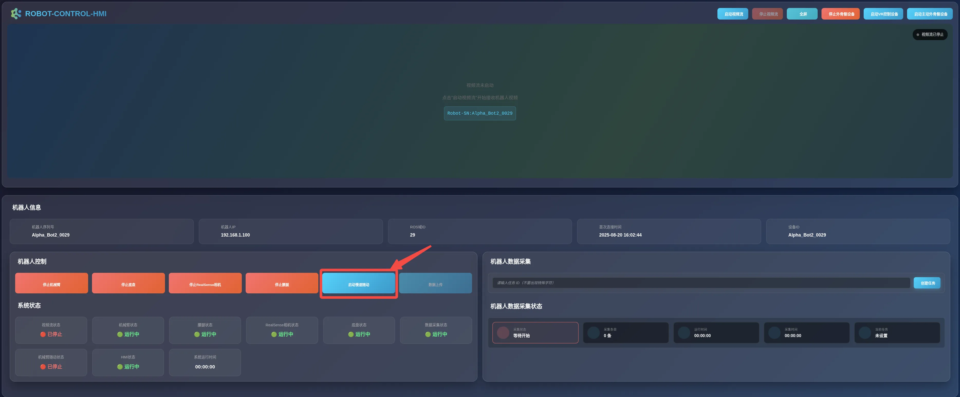
-
A prompt message as shown below will appear. The robotic arm will slowly move to the pose of the teleoperation arm. After confirming that the pose is normal, click the
OKbutton to switch to fast follow-up.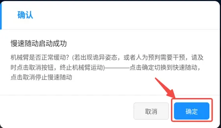
-
Click the
OKbutton in the pop-up window below to switch to Fast Follow-Up.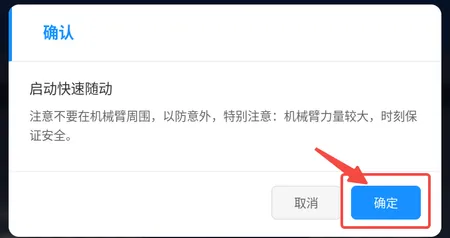
-
Once started successfully, the blue Start
Slow Follow-Upbutton will change to the redStop Fast Follow-Upbutton. Also confirm that the follow-up status in theSystem Statuspanel isFast Follow-Up.
Starting the Torso
Section titled “Starting the Torso”-
After ensuring that the camera and the video stream have been successfully started, click the
Start Torsobutton in theRobot Controlpanel.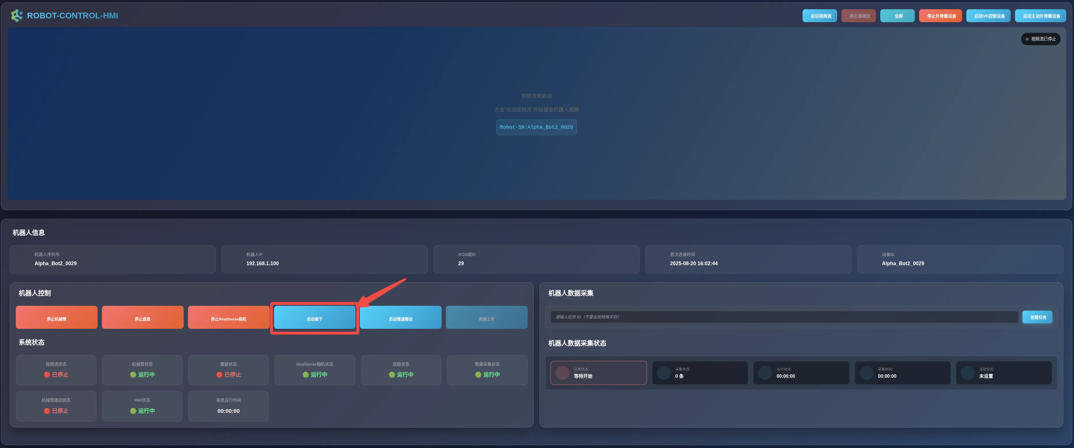
-
A prompt message as shown below will appear; please wait patiently.
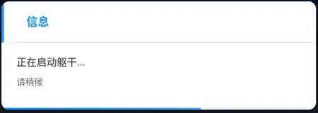
-
Upon successful startup, the torso will enter a self-check state. The
Start Torsoblue button will change to a redStop Torsobutton, and theTorso Statusin theSystem Statuspanel will displayRunning.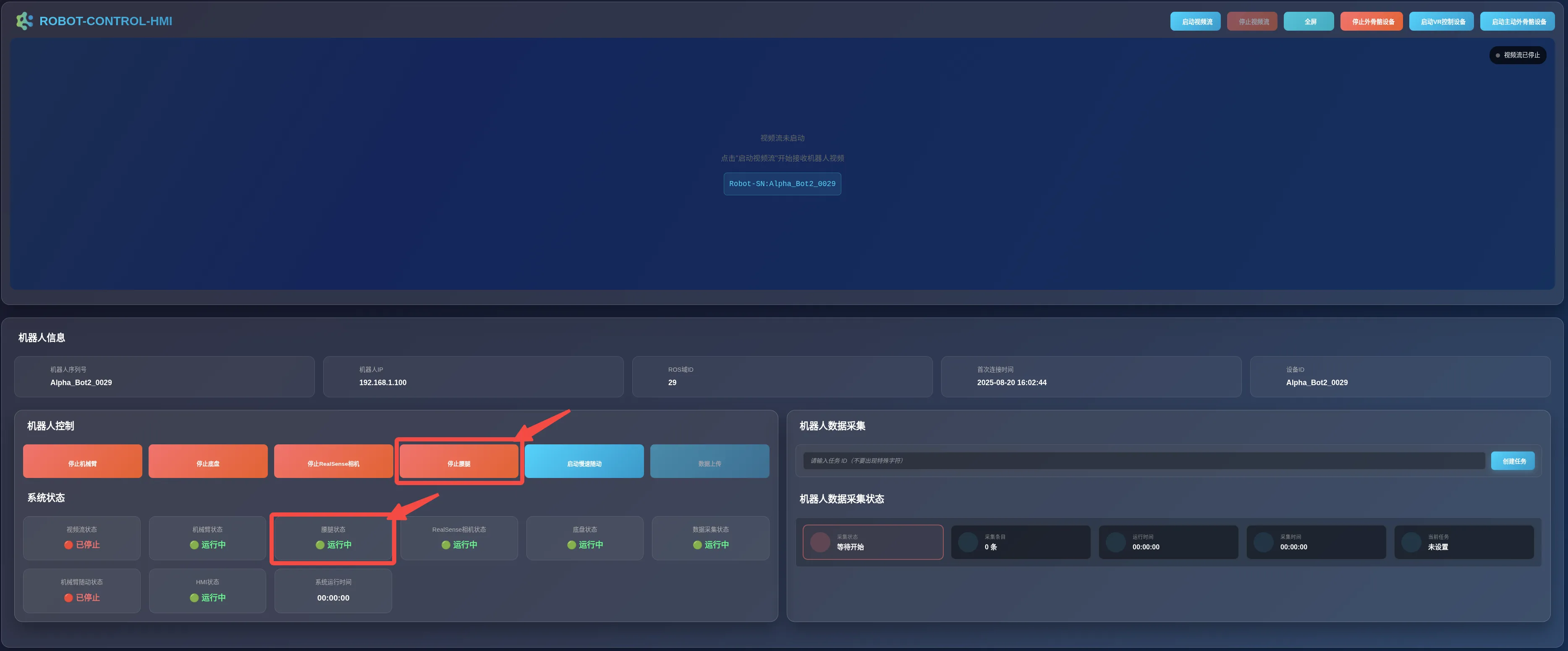
Starting the Chassis
Section titled “Starting the Chassis”-
Rotate the chassis knob to
Auto Modeand disconnect the charging cable. -
After ensuring that the camera and the video stream have been successfully started, click the
Start Chassisbutton in theRobot Controlpanel.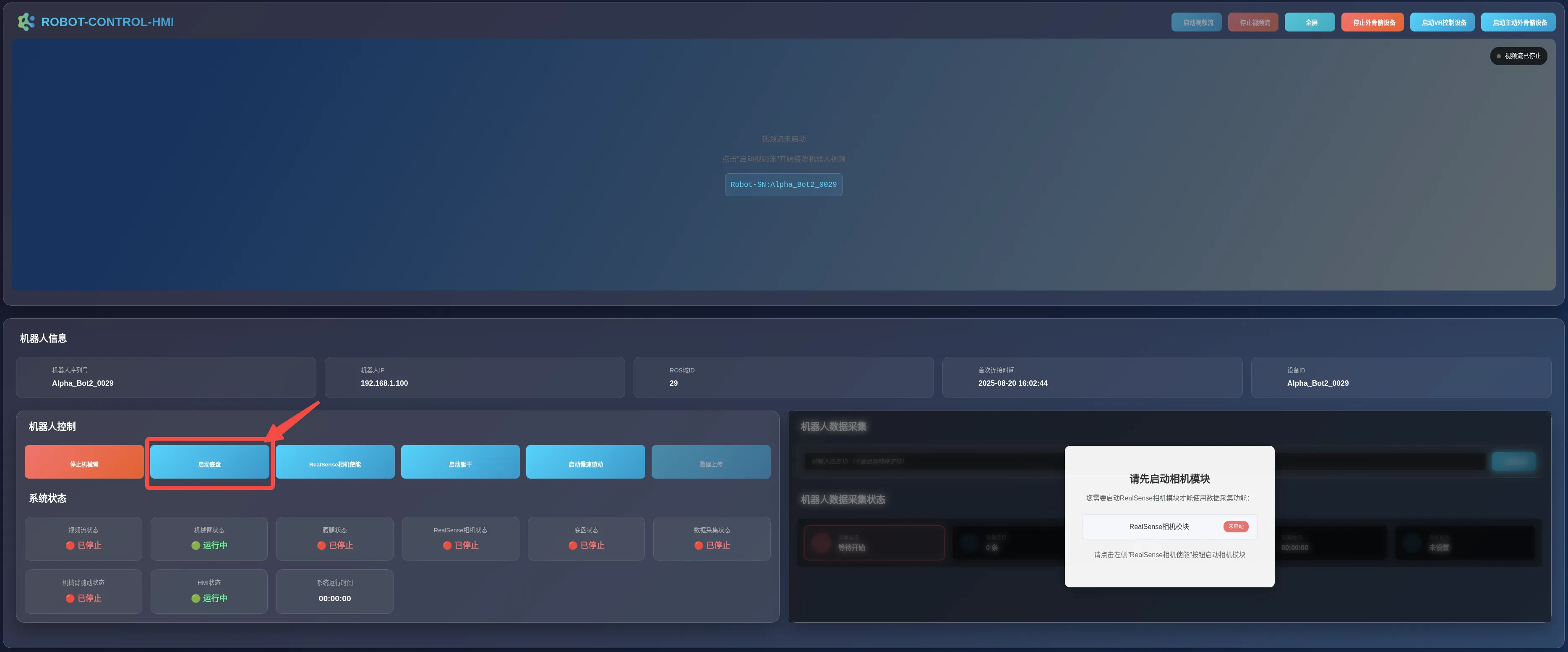
-
A prompt message as shown below will appear; please wait patiently.
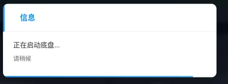
-
Upon successful startup, the chassis will enter a self-check state. The
Start Chassisblue button will change to a redStop Chassisbutton, and theChassis Statusin theSystem Statuspanel will displayRunning.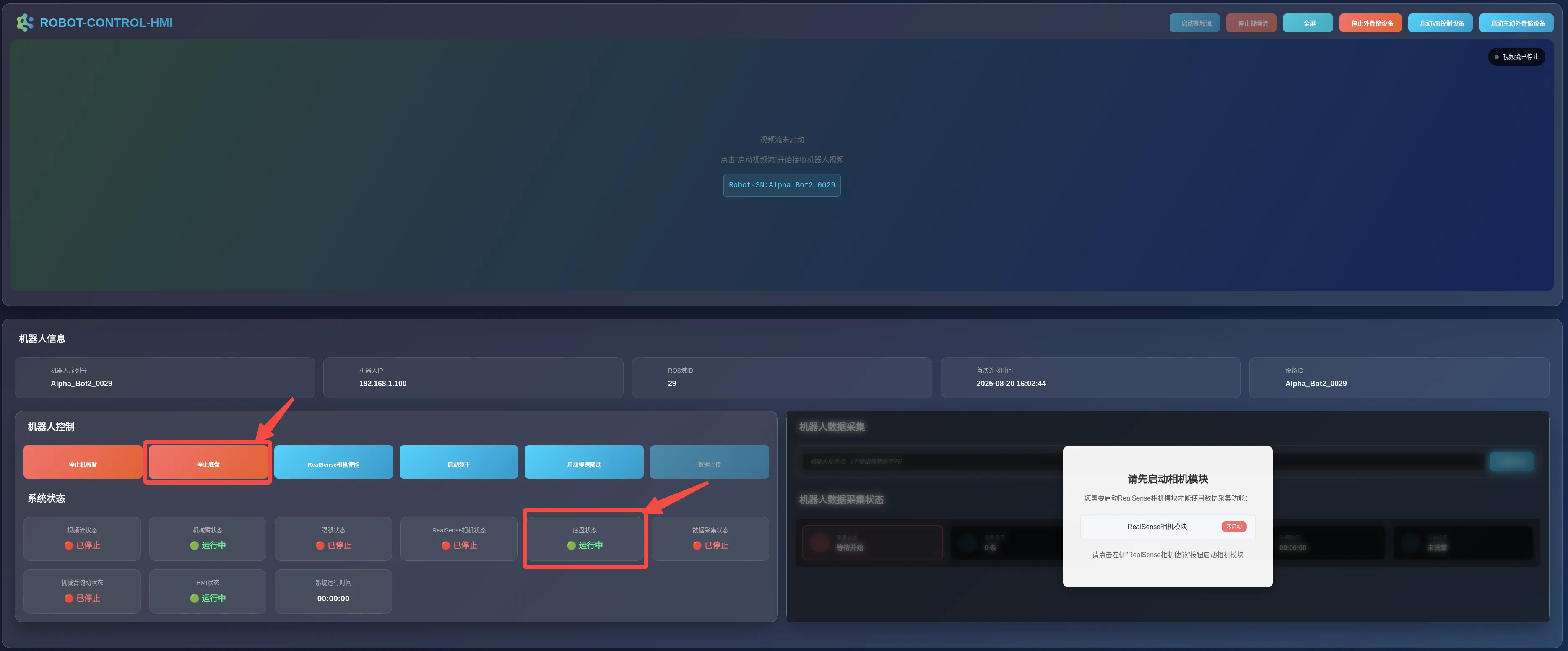
Using the Controller
Section titled “Using the Controller”After starting the exoskeleton device, you can use the controller to control the robot.
-
Ensure that the controller receiver is connected to the USB port of the industrial PC and that the controller has sufficient battery power.
-
When using the controller for the first time, the controller mode must be configured to
Android Mode -> ReceiverMode.Configuration method: Press and hold the HOME button for 3 seconds to enter the mode selection interface, then select
Android Mode -> Receiver. -
On the industrial PC, open a terminal and enter the following command:
Terminal window ros2 run joy joy_node -
You can control the neck, waist-legs, and chassis respectively through the controller buttons.
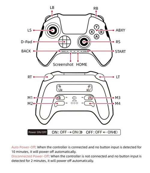
Operation Description Move Chassis
- Move forward/backward: LB + Left Stick Y
- Turn left/right: LB + Left Stick X
Control Neck
- Turn head left/right: Right Stick X
- Tilt head up/down: Right Stick Y
Control Waist/Legs
- Raise waist/legs: RT + A
- Lower waist/legs: RT + X
- Rotate waist right: LT + A
- Rotate waist left: LT + X
- Move waist forward/backward: Left Stick Y
Data Acquisition
Section titled “Data Acquisition”After starting the exoskeleton device, you can acquire data from the Exoskeleton Teleoperation Device using the Robot Data Acquisition function in the HMI interface.
Creating a Task
Section titled “Creating a Task”-
In the
Robot Data Acquisitionpanel, enter a Task ID and click theCreate Taskbutton.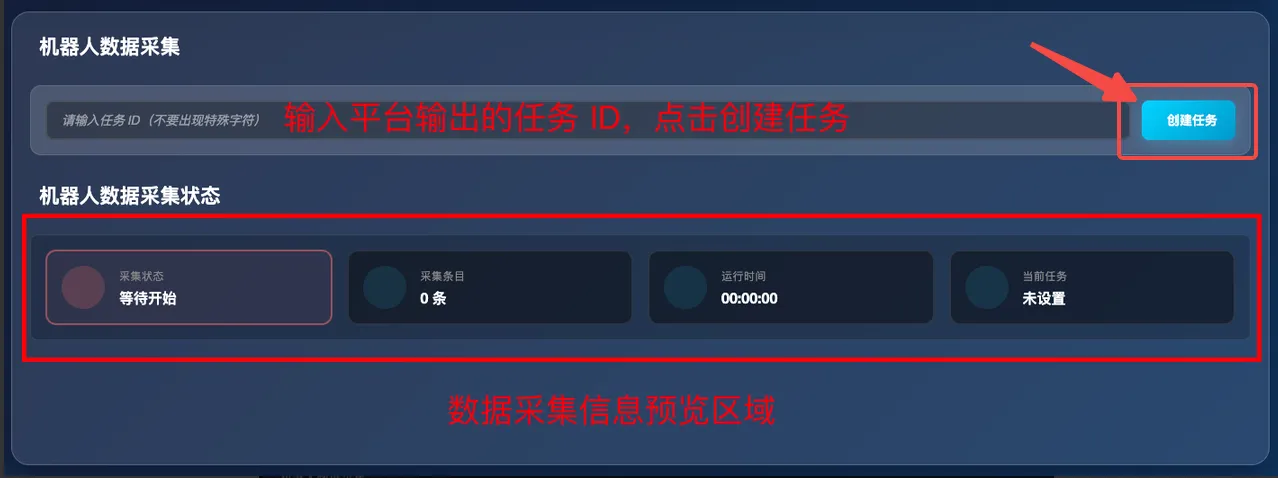
-
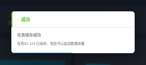
If it is a new task, a prompt message as shown below will pop up on the page.
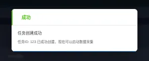
Click the blank area outside the pop-up window to close it.
-
If the Task ID already exists, a prompt message as shown below will pop up on the page. Click the
OKbutton to resume the existing task.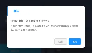
Click the blank area outside the pop-up window to close it.
-
-
Click the
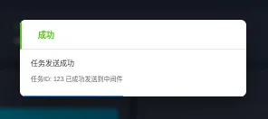
Send Taskbutton. A pop-up prompt will appear after successful sending.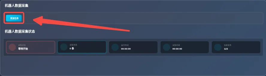
-
At this time, a prompt message as shown below will pop up on the page. Click the blank area outside the pop-up window to close it.
Starting Data Acquisition
Section titled “Starting Data Acquisition”After successfully creating a task, you can start acquiring data.
-
Use any of the following three methods to start data acquisition.
- Click the
Start Acquisitionbutton.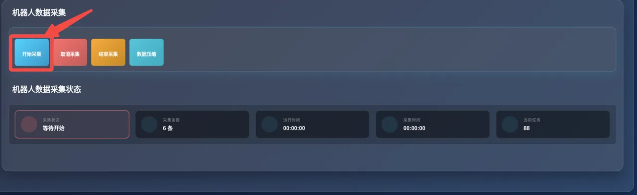
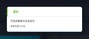
- Press the
Ctrl+3keyboard shortcut. (Note: Only keep the HMI page open in the browser; do not open any other pages. The existing shortcut key conflicts with the browser’s tab-switching functionality.) - Press the middle button of the foot pedal.
- Click the
-
Once data acquisition starts, the
Acquisition Statusin theRobot Data Acquisition Statuspanel will change fromWaiting to StarttoAcquiring, and the acquisition timer will begin counting.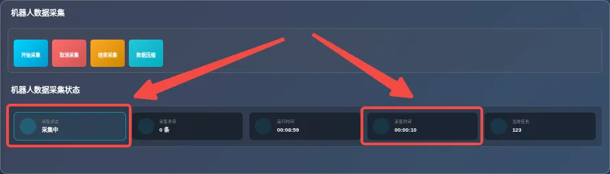
Canceling Acquisition
Section titled “Canceling Acquisition”During the acquisition process, you can cancel acquisition at any time.
-
Use any of the following three methods to cancel data acquisition.
- Click the
Cancel Acquisitionbutton.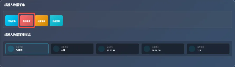
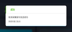
- Press the
Ctrl+4keyboard shortcut. (Note: Only keep the HMI page open in the browser; do not open any other pages. The existing shortcut key conflicts with the browser’s tab-switching functionality.) - Press the right button of the foot pedal.
- Click the
-
After acquisition is canceled, the
Acquisition Statusin theRobot Data Acquisition Statuspanel will change fromAcquiringtoWaiting to Start. The running time will stop counting, and the acquisition time will reset to zero.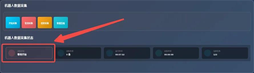
Ending Acquisition
Section titled “Ending Acquisition”After data acquisition is complete, you need to manually end the acquisition process.
-
Use any of the following three methods to end data acquisition.
- Click the
End Acquisitionbutton.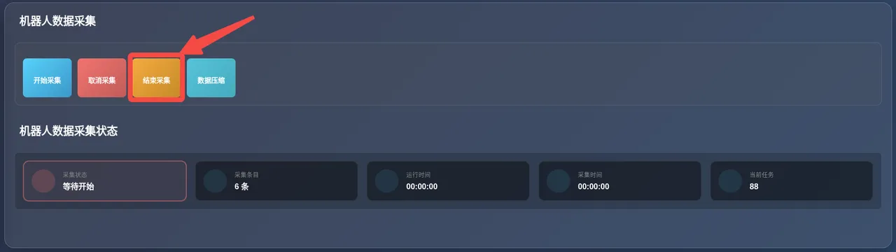
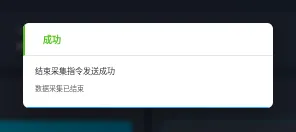
- Press the
Ctrl+3keyboard shortcut. (Note: Only keep the HMI page open in the browser; do not open any other pages. The existing shortcut key conflicts with the browser’s tab-switching functionality.) - Press the middle button of the foot pedal.
- Click the
-
After acquisition ends, the
Acquisition Statusin theRobot Data Acquisition Statuspanel will change fromAcquiringtoWaiting to Start. The running time will stop counting, the acquisition time will reset to zero, one data entry will be written to disk, and the acquisition entry count will increment by 1.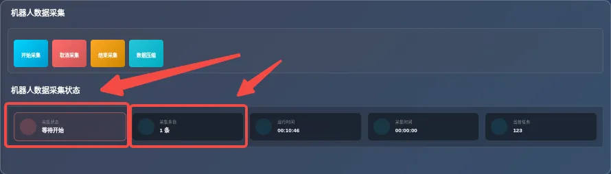
Compressing Data
Section titled “Compressing Data”After data acquisition, you need to compress data for easier subsequent upload and use. Before proceeding, ensure you have completed at least one data acquisition.
-
Click the
Data Compressionbutton.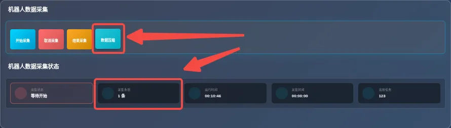
-
In the pop-up window below, enter a task name for compression, then click
Start Compression.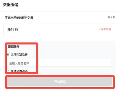
-
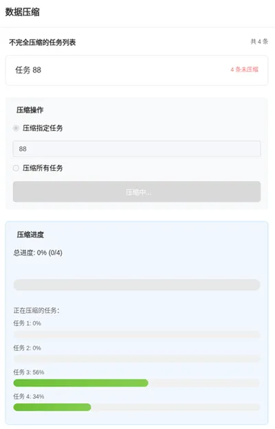
Wait for the compression process to finish. Click the blank area outside the window to close it.
Uploading Data
Section titled “Uploading Data”After data acquisition and compression, you can use the Data Upload function to upload data. Before proceeding, ensure you have completed at least one data acquisition and compression.
-
Click the
Data Uploadbutton.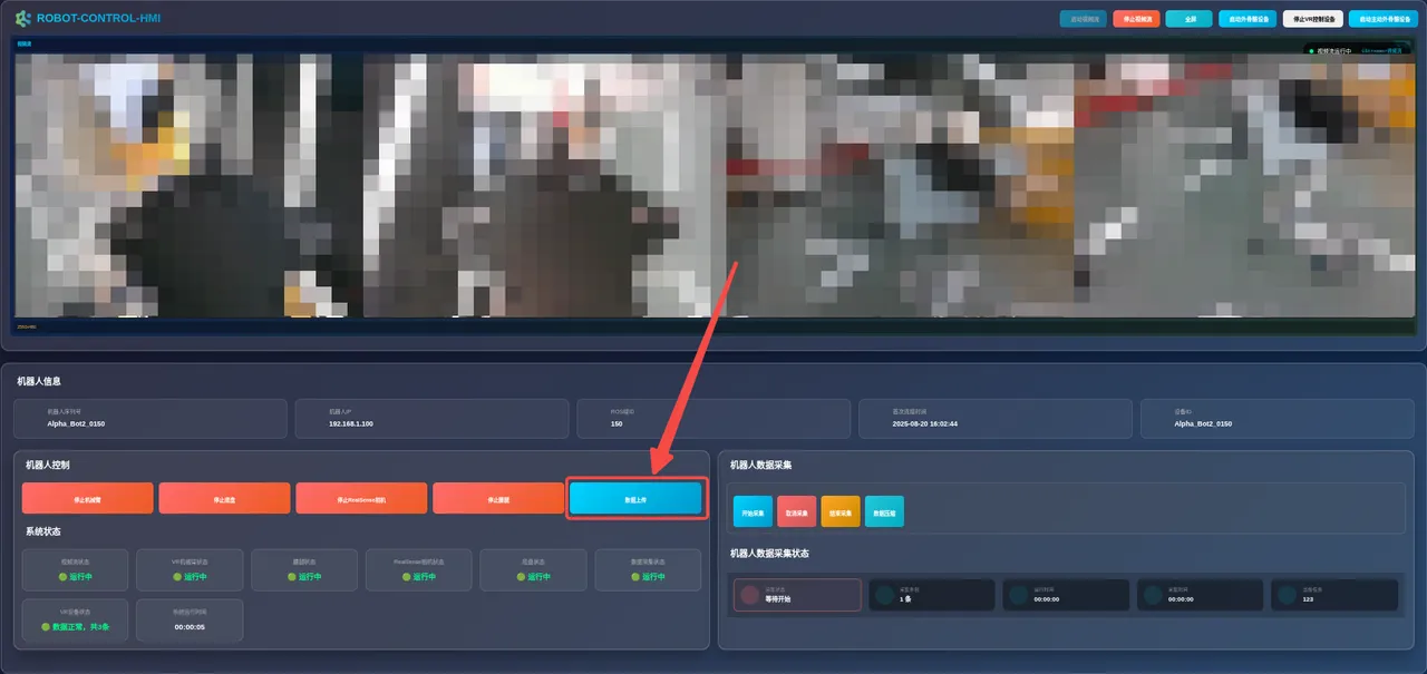
-
In the pop-up window below, please wait patiently for the data upload to complete and confirm that the number of uploaded files is correct. If you need to cancel the upload, click the
Cancel Uploadbutton.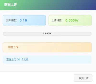
Using the Foot Pedal
Section titled “Using the Foot Pedal”| Button | Description |
|---|---|
| Middle Button | Start or stop data acquisition |
| Right Button | Cancel acquisition |
| Left Button | Add markers at different phases of long-duration tasks to facilitate data segmentation and training verification. |
Zero Calibration
Section titled “Zero Calibration”The zero calibration operation is only required after disassembling or assembling the structure. When the pose of the robotic arm is inconsistent with that of the teleoperation arm, and no over-limit is displayed on the AI2-HMI interface, it may be a zero position abnormality. Please contact us for assistance.