

Getting Started
Welcome to using the Exoskeleton Teleoperation Device! This document guides you through the initial steps, including unboxing and connection, to prepare you for subsequent use.
Unboxing
Section titled “Unboxing”After receiving the Exoskeleton Teleoperation Device, follow the steps below to unbox it:
-
Inspect the packaging box to ensure it is intact.
-
Refer to the list below to ensure no parts are missing or damaged.
Item Quantity Item Quantity Left Teleoperation Arm 1 Industrial PC 1 Right Teleoperation Arm 1 Monitor 1 Mobile Stand 1 Keyboard & Mouse 1 Counterweight 1 Foot Pedal 1 Storage Basket 1 Fastener Kit 1 Telescopic Hook Balancer 4 Tool Kit 1
Assembly
Section titled “Assembly”Before assembling, please review the final assembly diagram and the required item list to understand the connection relationships between components.
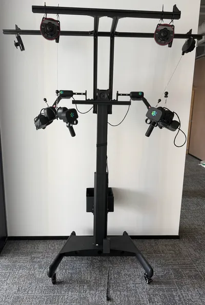
| Item | Quantity | Item | Quantity |
|---|---|---|---|
| Front Top Load-Bearing Bar (800mm Aluminum Profile) | 1 | Chassis | 1 |
| Rear Top Load-Bearing Bar (1550mm Aluminum Profile) | 1 | Casters | 4 |
| Top Side Bars (540mm Aluminum Profile) | 2 | Angle Brackets | 10 |
| Side Connecting Bars (600mm Aluminum Profile) | 2 | Telescopic Hook Balancers | 4 |
| Arm Load-Bearing Bar (460mm Aluminum Profile) | 1 | Storage Basket | 1 |
| Mounting Adapter | 1 | Counterweight | 1 |
| L-Shaped Arm Connectors | 2 | Bumper End Caps | 6 |
| Teleoperation Arms | 2 | Hex Socket Screws M6*30/35 | 8 |
| End-Effector Grips | 2 | Support Bar | 1 |
Next, follow the steps below to complete the assembly.
-
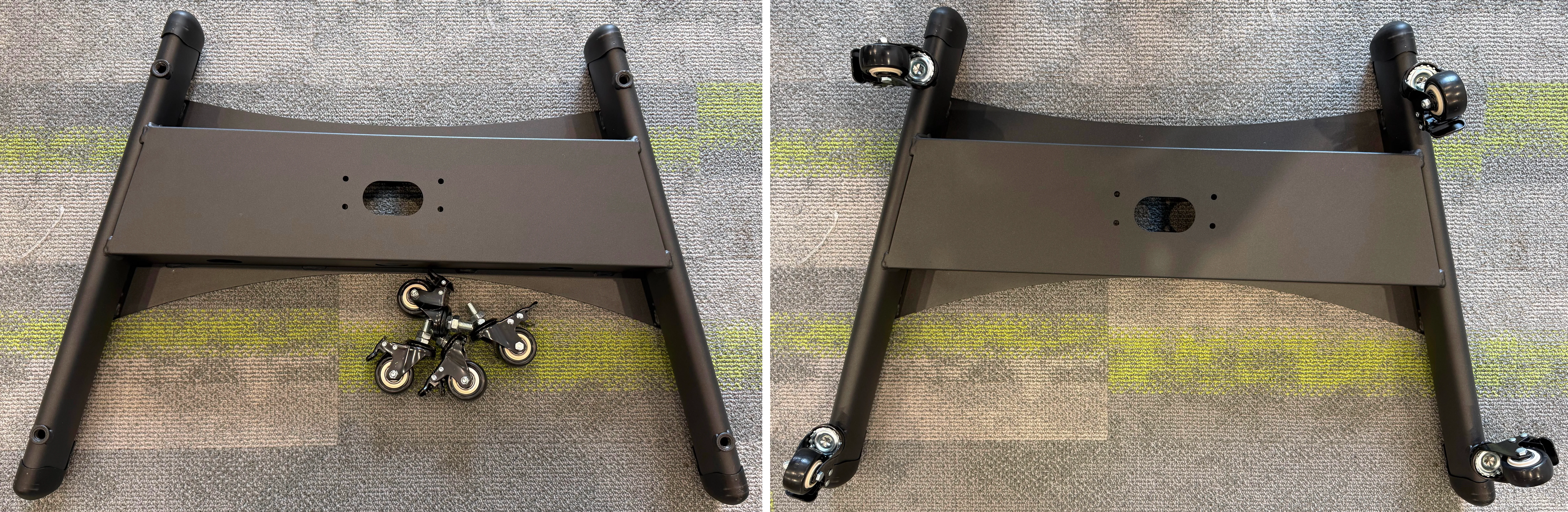
Install the four casters onto the chassis.
-
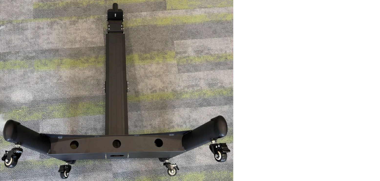
Install the support bar onto the chassis.
-
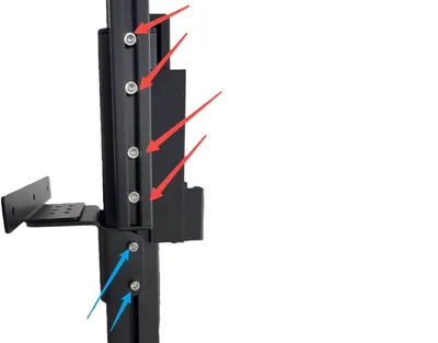
Using M6*35 screws, install the 600mm aluminum profiles (side connecting bars) and the teleoperation arm mounting base onto the support bar.
-
First, install the 540mm aluminum profiles (top side bars) onto the 600mm aluminum profiles (side connecting bars). Then, install the 800mm and 1550mm aluminum profiles (front and rear top load-bearing bars) onto the front and rear ends of the 540mm aluminum profiles (top side bars), respectively.
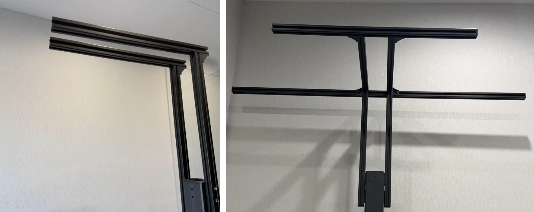
-
First, install the mounting adapter onto the teleoperation arm mounting base. Then, install the 460mm aluminum profile (arm load-bearing bar) onto the mounting adapter. Finally, install the bumper end caps onto both ends of the 460mm aluminum profile.
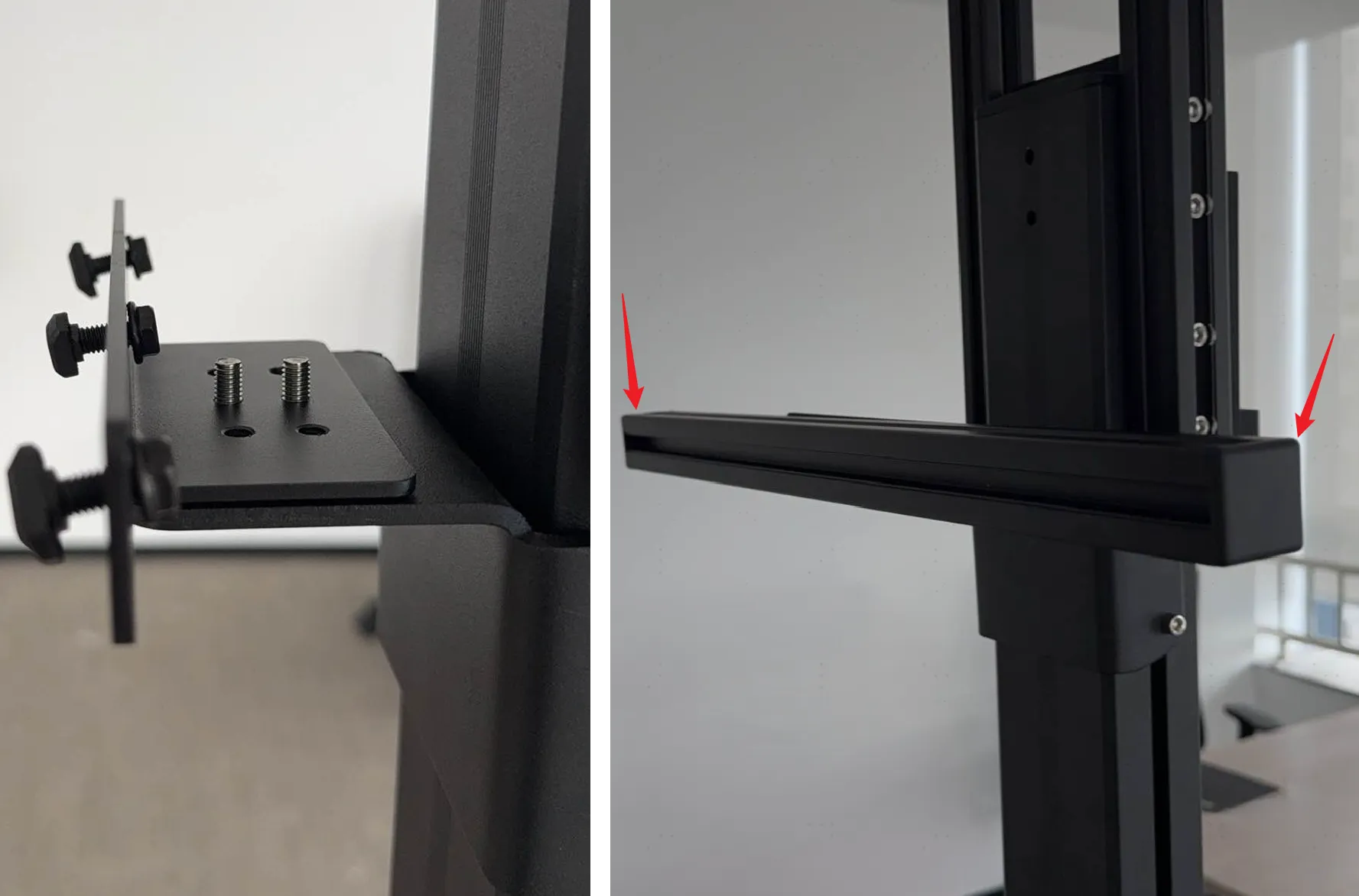
-
Install the left and right teleoperation arms onto the arm load-bearing bar.
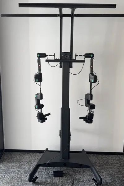
-
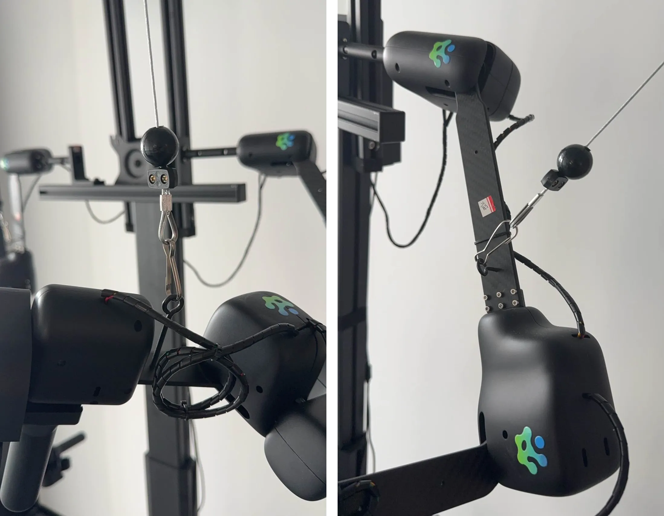
First, install angle brackets onto both ends of the front and rear top load-bearing bars. Then, use cable ties to secure the four telescopic hook balancers to the front and rear load-bearing bars (excess cable tie length may be trimmed). Finally, attach the suspension hooks to the teleoperation arms.
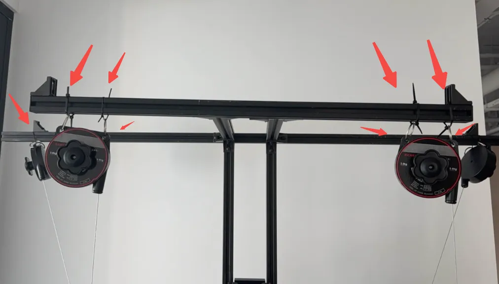
-
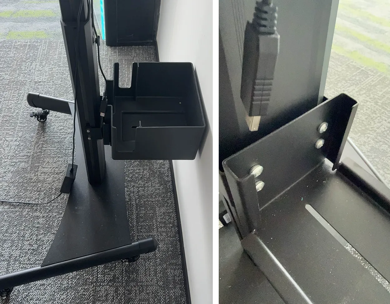
Fix the storage basket at the bottom of the support bar and place the counterweight inside to maintain stand stability.
-
The assembly of the exoskeleton teleoperation device is now complete.
Connection
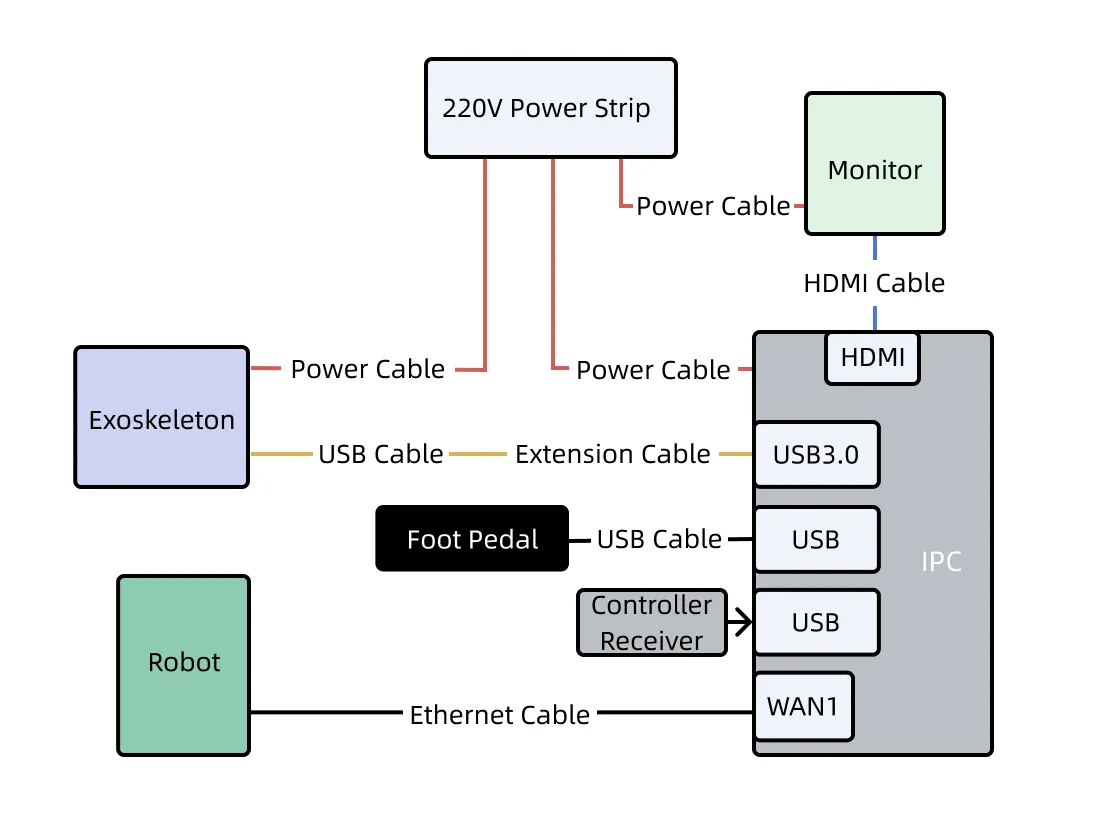
Section titled “Connection”After assembly, connect all components according to the diagram below.
Next, please refer to the Product Introduction for detailed information about the exoskeleton teleoperation device and its electrical characteristics, or skip to Common Operations to start using the device to perform tasks.